Do one of the following:
Click the Options tool button (![]() ) on the X-Hardware toolbar.
) on the X-Hardware toolbar.
Choose Hardware > Options in the X-Solids menu.
Type xoptions in the command bar, then press Enter.
Do one of the following:
Click the Options tool button (![]() ) on the X-Hardware toolbar.
) on the X-Hardware toolbar.
Choose Hardware > Options in the X-Solids menu.
Type xoptions in the command bar, then press Enter.
The X-Hardware Setup dialog box displays:
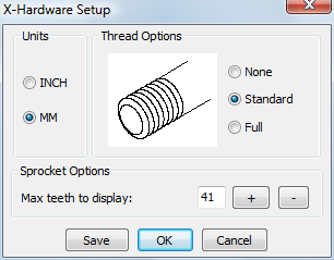
Choose your preferences.
Click the OK button to save the options.
Do one of the following:
Click the All
Hardware tool button (![]() ) on the X-Hardware toolbar.
) on the X-Hardware toolbar.
Choose Hardware > All Hardware in the X-Solids menu.
Type xhardware in the command bar, then press Enter.
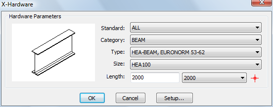
The X-Hardware dialog box displays:
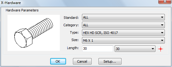
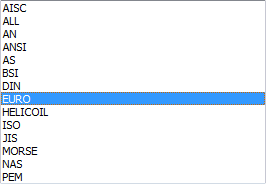
Choose a specifications standard from the
Standard list button: e.g.
Euro.
The choice of a standard limits the number of options on the next
list buttons.
Choose a category from the Category list button: e.g. Beam
The choice of a category limits the number of options in the next list buttons.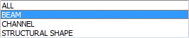
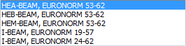
Choose a type from the Type list button: e.g. HEA-BEAM, EURONORM 53-62.
Choose a size from the Size list button.
Only sizes for the selected type are available in the list.
To define the length of the X-Hardware solid, do one of the following:
Type the length in the Length field.
Choose a length from the Length list button.
Click the Pick
Points button (![]() ).
).
The X-Hardware dialog box closes
temporarily.
You are prompted in the command bar to specify two points to define
the length.
After specifying the second point the X-Hardware dialog box reopens.
Click the OK button
to create the X-Hardware solid.
The X-Hardware dialog box closes.
The command bar reads: Insert point:
Specify a point in the drawing.
The X-Hardware solid is placed along the Z-axis of the current
UCS.
The length is measured along the negative Z-axis.
Do one of the following:
Specify a point in the drawing to place another copy of the X-Hardware solid.
Right click to stop.
Do one of the following:
Click the Change tool button (![]() ) on the X-Hardware toolbar.
) on the X-Hardware toolbar.
Click the Edit
tool button (![]() ) on the X-Solids toolbar.
) on the X-Solids toolbar.
Choose Edit in the X-Solids menu.
Type xhardwarechange in the command bar, then press Enter.
The X-Hardware dialog box displays, showing the settings of the selected X-Hardware solid:
(option) Choose a different standard from the Standard list button.
(option) Choose a different category from the Category list button.
(option) Choose a different Type from the Type list button.
(option) Choose a different Size from the Size list button.
(option) To modify the length of the X-Hardware solid, do one of the following:
Type the new length in the Length field.
Choose a length from the Length list button.
Click the Pick
Points button (![]() ).
).
The X-Hardware dialog box closes
temporarily.
You are prompted in the command bar to specify two points to define
the length.
After specifying the second point the X-Hardware dialog box reopens.
Click the OK button to apply the changes.
| © Menhirs NV. All rights reserved. |