Do one of the following:
Click the Attach
pdf tool button (![]() ) on the Insert toolbar.
) on the Insert toolbar.
Click the New
tool button (![]() ) on the Details toolbar of the Drawing
Explorer - PDF Underlays dialog.
) on the Details toolbar of the Drawing
Explorer - PDF Underlays dialog.
Type PDFattach in the command bar, then press Enter.
Commands: PDFATTACH, PDFLAYERS, PDFCLIP
PDF files can be attached as an underlay to a drawing file. Much like raster image files and external references (Xrefs) a PDF underlay is not part of the drawing, but is linked to it. In the parent drawing the path to the underlay is saved. You can edit the path to make sure the correct PDF is found. By default the folder of the parent drawing is search first. If the PDF underlay is not found there, the saved path folder is searched. If the PDF underlay is not found there either, Bricscad reports a 'Missing or invalid reference' in the drawing.
You can snap to the geometry in the PDF underlay if the PDFOSNAP system variable is On. Please notice that when snapping to geometry in a PDF underlay the precision is far less than snapping to entities in the drawing or an xref.
If a PDF underlay contains layers, you can control the display of these layers using the PDFLAYERS command.
The PDFCLIP command crops the display of a PDF. You can choose between a polygonal or a rectangular boundary. Each instance of the same PDF underlay file can have a different boundary.
Do one of the following:
Click the Attach
pdf tool button (![]() ) on the Insert toolbar.
) on the Insert toolbar.
Click the New
tool button (![]() ) on the Details toolbar of the Drawing
Explorer - PDF Underlays dialog.
) on the Details toolbar of the Drawing
Explorer - PDF Underlays dialog.
Type PDFattach in the command bar, then press Enter.
The Select PDF Underlay File dialog opens.
Select the file, then double click the file or
click the Open button on the
Select PDF Underlay File dialog.
The Attach PDF Underlay dialog
opens.
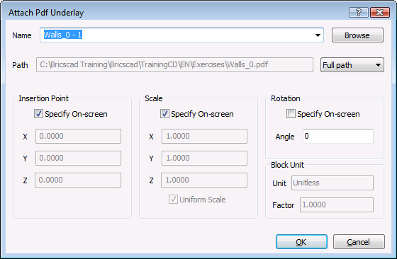
In case of a multi-page PDF, click the down arrow in the Name field, then select the page of the PDF you want to load.
Click the Path option button, then select either:
Full path: The full path will be searched when the drawing is loaded. If the overlay is not found there, the folder of the parent drawing is searched. If the overlay file is not found there either, "Missing or invalid reference" displays at the insertion point of the PDF overlay.
Relative path: The relative path, with respect to the folder of the parent drawing, will be searched when the drawing is loaded. If the overlay is not found there, the folder of the parent drawing is searched. If the overlay file is not found there either, "Missing or invalid reference" displays at the insertion point of the PDF overlay.
No path: Only the folder of the parent drawing is searched when the drawing is loaded. If the overlay file is not found there, "Missing or invalid reference" displays at the insertion point of the PDF overlay.
Choose whether you want to specify the Insertion Point, Scale and the Rotation angle on-screen or not.
Click the OK
button.
The Attach PDF Underlay dialog
closes.
Depending on the insertion options chosen in the previous step you are prompted to specify the Insertion Point, Scale and/or Rotation angle.
If you want to insert a second instance of a PDF that is already attached or another page of such underlay do the following:
Choose Drawing Explorer >
PDF Underlays... in the Tools
menu.
The Drawing Explorer - PDF Underlays
dialog opens.
Select the PDF underlay.
Do one of the following:
Right click and choose Insert in the context menu.
Choose insert in the Edit menu on the Drawing Explorer - PDF Underlays dialog.
The Drawing Explorer - PDF Underlays dialog closes.
Continue with steps 3 through 7 of the previous procedure.
To control the display of a PDF underlay
Click the frame of the PDF underlay.
The frame of the selected PDF highlights.
The properties of the underlay display in the Properties
Bar.
Under Misc, click Show underlay in the Properties Bar, then select Yes or No.
To set the layer display in a PDF underlay
Type PDFlayers in the
command bar, then press Enter.
The command bar reads: Select PDF underlay.
Click the frame of the PDF underlay.
The frame of the selected PDF highlights.
The Underlay Layers dialog opens.
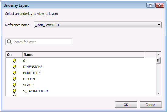
The icon in the On
column indicates the current state of the layers On (![]() ) or Off (
) or Off (![]() ).
).
Click the icon in the On column to toggle the display of a layer.
(option) Click the Search
for layer field, then type a layer name to search for a
layer.
Use wildcard characters (? or *) to limit the number of
layers in the list:
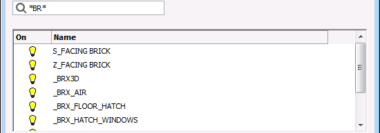
Layers with 'BR' in the layer name only.
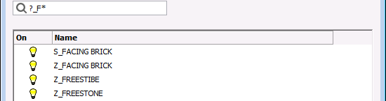
Layers of which the second and third character is '_F' only.
Do one of the following:
Click the Reference name button to select another PDF underlay.
Click the OK button to stop.
Type pdfclip in the
command bar, then press Enter.
The command bar reads: Select PDF underlay:
Click the frame of the PDF underlay.
The frame of the selected PDF highlights.
The command bar reads: Enter PDF clipping option
[ON/OFF/Delete/New] <New>:
A prompt menu displays:
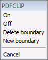
Do one of the following:
Choose New boundary in the prompt menu.
Press Enter to accept the New default command option.
The command bar reads: Enter PDF clipping type [Polygonal/Rectangular] <Rectangular>:
Do one of the following:
Press Enter to accept the Rectangular default command option to define a rectangular clipping boundary.
Type P, then press Enter to define a polygonal clipping boundary.
Define the clipping boundary.
The defining points must lie inside the frame of the PDF underlay.
If you click outside the PDF underlay the point is placed on the
PDF underlay frame.
To toggle the display of the clipped part of a PDF underlay
Click the frame of the PDF underlay.
The frame of the selected PDF highlights.
The properties of the underlay display in the Properties
Bar.
Under Misc, click Show clipped in the Properties Bar, then select Yes or No.
Type pdfclip in the
command bar, then press Enter.
The command bar reads: Select PDF underlay:
Click the frame of the PDF underlay.
The frame of the selected PDF highlights.
The command bar reads: Enter PDF clipping option
[ON/OFF/Delete/New] <New>:
A prompt menu displays:
Do one of the following:
Choose Delete boundary in the prompt menu.
Type D in the command bar, then press Enter.
The clipping boundary is deleted and the complete PDF underlay displays.
| © Menhirs NV. All rights reserved. |