A geometric constraint is a non-numerical relationship between the parts of a geometric figure.
Geometric constraints:
associate geometric entities together two by two (coincident, concentric, collinear, parallel, perpendicular, tangent, smooth, symmetric, equal)
specify a fixed angle (horizontal, vertical)
specify a fixed location (fix)
When a geometric constrained is applied to an entity:
the position of the entity is adjusted according to the applied constraint.
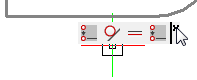
an icon displays next to the entity, to indicate the applied constraint. If multiple geometric constraints are applied, the icons are joined to a constraint bar.
If the SELECTIONPREVIEW system variable is set to 1 or 3, a blue icon displays next to the cursor when you move the cursor over entities that have constraints applied to them.
![]()
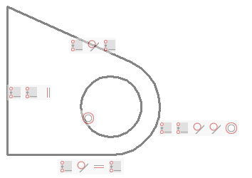
In the image below the endpoints of the three lines and the arc are joined by coincident constraints. The midpoint of the circle and the arc are made concentric. Two lines are forced to be tangent to the arc. One line has a vertical constraint (= parallel to the Y-axis of the current coordinate system), one line has a horizontal constraint (= parallel to the X-axis of the current coordinate system)
To control the display of constraint bars
Click the 2D Constraint
bar tool button (![]() ) on the 2D Constraints toolbar.
) on the 2D Constraints toolbar.
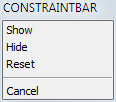
The command bar reads: Select option to [Show/Hide/Reset]
constraints:
A prompt menu displays:
Do one of the following:
Choose Hide or Show in the context menu.
Type H or S in the command bar, then press Enter.
The command bar reads: Select entities:
Select entities, then press Enter.
|
NOTE |
Constraint bars are always hidden when opening a drawing. |
To control the position of a constraint bar
By default constraint glyph bars are created close to the midpoint of the entity and are kept at that relative position when the entity position changes. You can drag the constraint bar to a different location. This new relative position is then maintained until the Reset option of the CONSTRAINTBAR command restores the default position of the constraint bar.
To relocate a constraint bar:
Place the cursor on the constraint bar.
Press and hold the left mouse button to move the constraint bar.
Release the left mouse button at the desired location.
To restore the default position of the constraint bars:
Click the 2D Constraint
bar tool button (![]() ) on the 2D Constraints toolbar.
) on the 2D Constraints toolbar.
The command bar reads: Select option to [Show/Hide/Reset]
constraints:
A prompt menu displays:
Do one of the following:
Choose Reset in the prompt menu.
Type R in the command bar, then press Enter.
The command bar reads: Select entities:
Select entities, then press Enter.
Working with the constraint bar
Using the constraint bar you can:
Control a constraint.
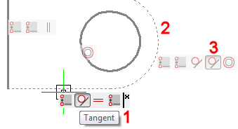
Move the cursor over a constraint icon.
A tooltip displays, indicating the constraint type (1)
The associated entity highlights (2)
The corresponding icon on the constraint bar of the associated
entity highlights (3)
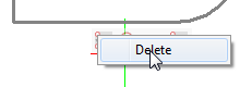
Delete a constraint.
Move the cursor over the constraint icon, then right click.
Click Delete.
The constraint is deleted and the icon is removed from this
constraint bar and from the constraint bar of the corresponding
entity.
Hide the constraint bar of an entity.
Move the cursor of the constraint bar, then click the Close button.
To delete a single constraint: right click the constraint icon, then click the Delete button.
To delete all constraints from a selection set:
Click the Delete 2D
Constraints icon (![]() ) on the 2D Constraints toolbar.
) on the 2D Constraints toolbar.
The command bar reads: Select entities to delete all
constraints:
Select the entities you want to delete the constraints from.
Right click to stop selecting entities and delete all constraints from the selection set.
A fix geometric constraint (![]() ) forces a point or an entity
to a fixed location.
) forces a point or an entity
to a fixed location.
If a fix geometric constraint is applied to a line or a polyline segment, the angle of the line or polyline segment is fixed. The endpoints can still be moved.
If you fix an arc or a circle, the center point is fixed too.
|
NOTE |
It is recommended to apply a fix constraint to important geometric features in your design. This prevents the geometry from moving unexpectedly when you edit the design. |
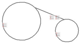
A coincident geometric constraint can be applied to two points or to a point and an entity. The endpoints of lines, polylines, splines, rays and arcs (circular and elliptical) and the center point of circles, ellipses and arcs (circular and elliptical) are accepted. These points can be made coincident (= to lie on the entity or on the extension of the entity) with a line, a polyline segment, a circle or an arc (circular and elliptical).
|
|
|
Coincident constraints between the endpoint of a line and two circles |
If the endpoints or center points of entities already coincide, the Autoconstraint option of the GcCoincident command automatically applies coincident constraints to such points.
Click the Coincident
tool button (![]() ) on the 2D Constraints toolbar.
) on the 2D Constraints toolbar.
The command bar reads: Select first point or [Entity/Autoconstrain]
<Entity>:
A prompt menu displays:
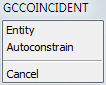
Do one of the following:
Press Enter.
Choose Entity in the prompt menu.
The command bar reads: Select an entity:
Select the entity.
The entity highlights.
The command bar reads: Select point or [Multiple]:
Snap to the endpoint of an entity or the center
point of a circle or an arc.
The selected point is forced to lie on the selected entity (or its
extension).
|
NOTE |
If you choose Multiple in step 3, you can select multiple points. |
|
|
|
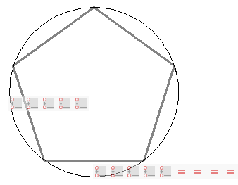
By applying coincident constraints between the pentagon vertices and the circle, and equal constraints between one side and the four other sides, the circle radius defines the size of the pentagon. |
|
|
|
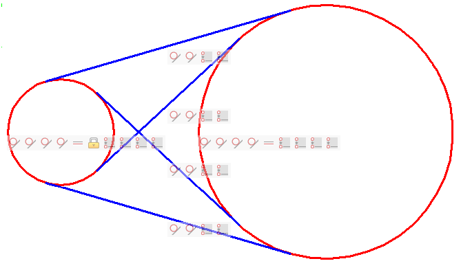
Coincident constraints between the endpoints of the tangent lines and the circles prevent the tangent lines to extend beyond the tangent points. |
|
|
|
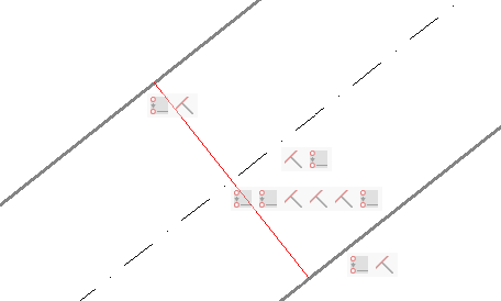
Coincident constraints are used to: - force the endpoints of the red line to lie on
the bold lines; The bold lines and the dash-dot line have a perpendicular constraint with the red line. As a result the dash dot line will always lie in the middle of the two bold lines. |
Using horizontal and vertical constraints
Horizontal and vertical geometric constraints force two points, a line or a polyline segment to be parallel to the X-axis (horizontal) or the Y-axis (vertical) of the current coordinate system. Therefore these constraints can be used to keep lines at a fixed angle, rather than only horizontal or vertical.
Align the X-axis of the coordinate system to the desired angle.
Type UCS in the command bar, then press Enter.
Choose Z in the prompt menu or type Z, then press Enter.
Type the angle, then press Enter.
Click the Horizontal
tool button (![]() ) on the 2D Constraints toolbar.
) on the 2D Constraints toolbar.
The command bar reads: Select an entity or [2Points]
<2Points>:
Click the line or polyline segment.
The selected entity is constrained to be parallel to the X-axis of
the current UCS.
(option) Restore the WCS: Type UCS in the command bar, then press Enter twice.
|
NOTE |
Use the Vertical tool in the above procedure to constrain entities to be parallel to the Y-axis of the current UCS. |
| © Menhirs NV. All rights reserved. |