Lights
Commands: DISTANTLIGHT,
GEOGRAPHICLOCATION,
LIGHT,
LIGHTLIST,
POINTLIGHT,
SPOTLIGHT,
SUNPROPERTIES,
WEBLIGHT
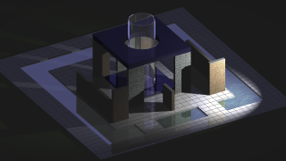
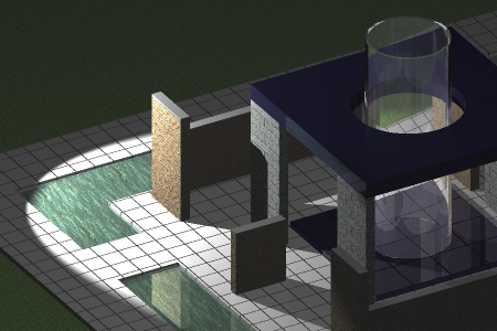
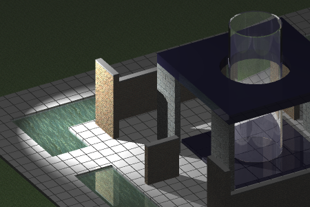
Lighting is the key to make the viewer believe to look at a
realistic scene.
Lighting glossary
- Ambient light:
light from an unspecified source.
- Back light: light
that adds depth and dimension by creating highlights.
- Distant light:
light that is cast evenly throughout a scene with shadows all in
the same direction.
- Fall-off: the
attenuation or decrease in brightness the further from the light
source.
- Fill light: the
light that brightens dark areas and softens shadows from the main
light.
- Point light: light
that shines in all directions from a central spot.
- Spot light:
focusable light that is aimed in one area.
- Photometric web: a
3D representation of the light intensity distribution of a light
source.
- Web light:
approximates real-world light distribution using a 3D
representation of the light intensity. Web lights can be created
only if the LIGHTINGUNITS
system variable is set to 1 (American lighting units) or 2
(International lighting units).
- Attenuation: the
fall-off in brightness the further from the light source.
System variables
LIGHTINGUNITS (Lighting units):
-
0: No lighting
units are used. Enables generic lighting.
-
1: Enables
American lighting units: Foot-Candles
-
2: Enables
International lighting units: Lux.
DEFAULTLIGHTING (Default lighting): A distant light
that follows the view direction. This setting can be different per
viewport.
LINEARCONTRAST (Linear contrast): Specifies the
ambient light intensity. Values between -10 and 10 are accepted. A
value of -10 results in maximum ambient light. A value of 10
results in no ambient light.
LINEARBRIGHTNESS (Linear brightness): Specifies a
scaling factor for the light intensity. Values between -10 and 10
are accepted. The default value is 0 (no scaling). Negative values
decrease the light intensity, positive values increase the light
intensity. This setting can be different per viewport.
General properties
The general properties are common to all lights:
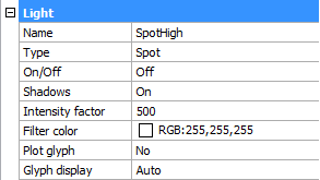
- Name: a user defined name for the light.
- Type: defines the type of light: spot, point, web or
distant.
- On/Off: specifies whether the light is turned on or
off.
- Shadows: specifies whether the light casts shadows or
not. Turning shadows off to increases performance.
- Intensity factor: multiplies the Lamp Intensity property, the result is the
Resulting Intensity.
- Filter color: defines the color of the light.
- Plot glyph: if on, the light glyph is plotted.
- Glyph display: controls the display of the light
glyph
Photometric light properties
LIGHTINGUNITS = 1 (American units) or 2 (International
units).
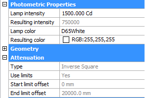
- Lamp intensity:
Defines the brightness of the light. The lamp intensity is
expressed in candela (cd) which is the SI base unit of luminous
intensity: the power emitted by a light source in a particular
direction, weighted by the luminosity function (a standardized
model of the sensitivity of the human eye to different wavelengths,
also known as the luminous efficiency function)
- Resulting
intensity: the product of the lamp intensity and and
intensity factor.
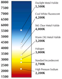
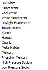
- Lamp color:
defines the inherent color of the light or color temperature in
Kelvin or standards.
|
|
|
|
color
temperatures
|
lamp
color list
|
- Resulting color:
this is the final color of the light: a combination of the lamp
color and the filter color.
- Photometric web:
If the light type is Web,
Photometric Web and Web offsets are available (not implemented
yet).
Geometry properties
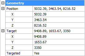
- Position: controls the location of the
light.
- Target: defines the target point for point lights,
spotlights and weblights
- Targeted: switches the target property on/off.
Attenuation properties
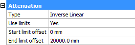
In the real world, an object appears darker if it is farther
away from the light source. The attenuation properties define how
the light diminishes over distance. Attenuation does not
apply to photometric lights.
An alternative method to control the distance a light shines is
the use of limits, which define the points from where a light
starts to shine and where it stops. Using limits decreases the time
needed to calculate the illumination of a scene.
Attenuation properties apply to spot lights and point
lights.
- Type: the options are none, inverse
linear and inverse square
- None: no
attenuation. The distance to the light source has no
influence.
- Inverse Linear:
the attenuation is the inverse of the linear distance from the
light: at a distance of 2 units from the light source, light is
half as strong; at a distance of 4 units, light is one quarter as
strong.
- Inverse Square:
the attenuation is the inverse of the square of the distance from
the light: at a distance of 2 units, light is one quarter as
strong; at a distance of 4 units, light is one sixteenth as strong.
- Use Limits: if this property is set to Yes, the
Start limit offset and End limit offset fields become active.
- Start limit
offset: defines the point where the light starts to shine,
measured from the center of the light.
- End limit offset:
defines the point where the light stops to shine, measured from the
center of the light.
|
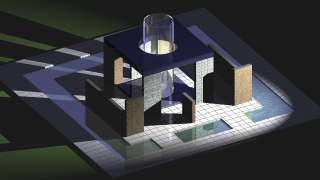
|
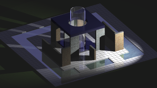
|
|
|
No
attenuation
|
Inverse linear attenuation
|
Inverse square attenuation
|
The Attenuation properties apply
to generic lights only (LIGHTINGUNITS = 0).
Inverse square attenuation is applied automatically for
photometric lights ( LIGHTINGUNITS = 1 or 2).
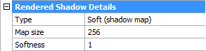
Rendered shadow details
-
Type: Sets the shadow type.
-
Sharp (raytraced): generates sharp edged shadows.
-
Soft (shadow map): generates realistic shadows with soft
edges.
-
Soft (sampled): Not supported yet
-
Map size: specifies the amount of
memory for shadow calculation. Click the field, then select a value
in the drop-down list (64/128/256/512/1024/2048/4096).
-
Softness: sets the softness of the
shadow map. Enter a value between 1 and 10.
Spotlight hotspot and falloff properties
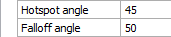
When a surface is illuminated by a spotlight, there is an area
of maximum illumination (hotspot = 1) that is surrounded by an area
of lesser intensity (falloff = 2).
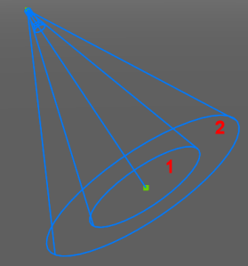
- Hotspot angle: angle of the central light cone
(defines the hotspot)
- Falloff angle: angle of the full light cone
|
|
|
|
Hotspot angle = 55, Falloff angle = 60
|
Hotspot angle = 30, Falloff angle = 60
|
The difference between the hotspot angle and the falloff angle
defines the area of lesser light intensity.
If the falloff angle and the hotspot angle are almost equal
the edge of light cone is rather sharp (left).
The greater the difference between both angles, the softer the
edge of the light cone (right).
To open the light list in the Drawing
Explorer
Do one of the following:
- Click the Light
List... button (
 ) on the Lights toolbar.
- Choose Drawing
Explorer > Lights in the Tools menu.
- Choose Light
List.. in the View | Rendering |
Lights menu
- Type lightlist
or LL in the command bar, then press
Enter.
|
Icon
|
Tool name
|
Description
|
|

|
New light
|
Closes the Drawing Explorer -
Lights dialog, then guides you to the creation of a new
light in the drawing.
|
|

|
Delete light
|
Deletes the selected light.
|
|

|
Select in drawing
|
Closes the Drawing Explorer -
Lights dialog and selects the light's glyph in the
drawing.
The properties of the light display in the Properties
Bar.
|
|

|
Light ON
|
Click to switch light off.
|
|

|
Light OFF
|
Click to switch light on.
|
To define a light
- Do one of the following:
- Type light in
the command bar, then press Enter.
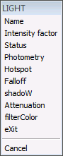
You are prompted: Enter light type
[Point/Spot/Web/Distant] <Point>:
A prompt menu displays:
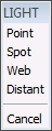
Choose a light type in the prompt menu.
- Click the tool button of the light type you
want to create on the Lights
toolbar:
-
 New spot light
 New point light
 New distant light
 New web light
- Do one of the following:
- Specify the source position in the
drawing.
- Type the coordinates of the source position
in the command bar and press Enter.
- Press Enter to accept the default
coordinates.
You are prompted: Specify target position
<0,0,-10>:
- Do one of the following:
- Specify the target position in the
drawing.
- Type the coordinates of the target position
in the command bar and press Enter.
- Press Enter to accept the default
coordinates.
You are
prompted: Enter an option to change: Name/Intensity
factor/Status/Photometry/Hotspot/Falloff/shadoW/Attenuation/filterColor/<eXit>:
A prompt menu displays:
- Do one of the following:
- Select Name
in the prompt box.
- Type N in the
command bar and press Enter.
You are prompted: Enter light name
<Spotlight1>:
- Do one of the following:
- Type a name in the command bar and press
Enter.
- Press Enter to accept the default name.
You are
prompted: Enter an option to change: Name/Intensity
factor/Status/Photometry/Hotspot/Falloff/shadoW/Attenuation/filterColor/<eXit>:
- Do one of the following:
- Click a light property in the prompt
menu.
- Type the capitalized letter of a light
property in the command bar and press Enter.
You are prompted to define the selected property in
the command bar.
- Do one of the following to conclude the creation
of the light:
- Choose Exit in the prompt menu.
- Press Enter.
|
NOTE
|
It is not possible to define a web light if the LIGHTINGUNITS system variable is zero (No
lighting units).
|
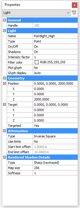
To edit
a light
- Select the light in the drawing.
If the Properties bar is not open yet, double click the light.
The properties of the selected light display in the
Properties Bar:
|
|
|
|
Generic light properties
|
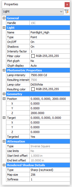
Photometric light properties
|
- To edit a property:
- Expand the settings group if needed.
- Select the property
- Edit the selected property.
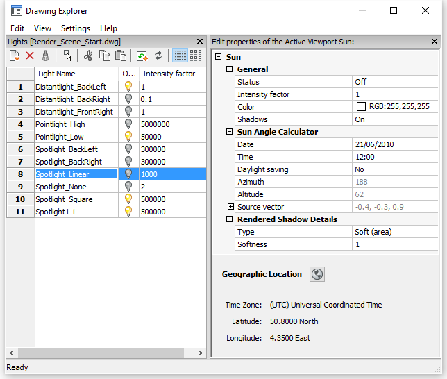
To define the sun properties
- Do one of the following:
- Click the Sun
Properties... tool button (
 ) on the Render toolbar.
- Type sunproperties or sun in the command bar, then press Enter.
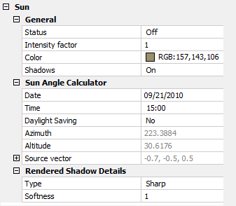
The Drawing Explorer -
Lights dialog displays, showing the sun properties in the
Editor pane.
- To edit a property:
- Expand the settings group if needed.
- Select the property
- Edit the selected property.
|
NOTE
|
When LIGHTINGUNITS
= 1 or 2, the Color property of the
sun cannot be edited.
|
To define the geographic
location
- Do one of the following:
- Click the Geographic
location... tool button (
 ) on the Render toolbar.
- Click the Geographic
location... tool button () on Editor pane of the Drawing
Explorer - Lights dialog.
- Type geographiclocation or geo in the command bar, then press Enter.
The Geographic
Location dialog displays:
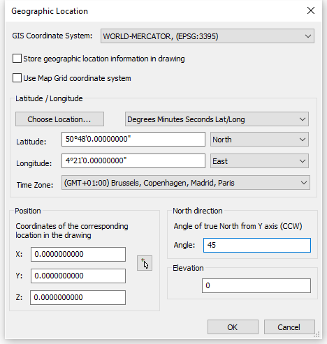
- (option) Check the Store
geographic location information in drawing option.
- (option) Check the Use Map
Grid coordinate system option.
- Do one of the following:
- Type the latitude and longitude of the
location in the Latitude and
Longitude fields and select the
appropriate hemisphere for each setting.
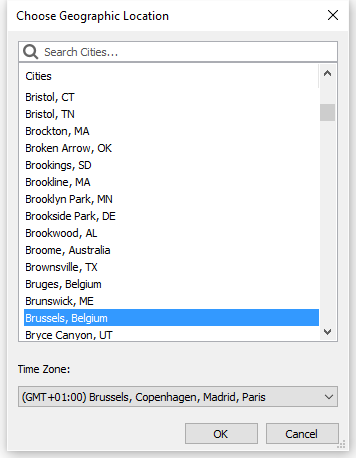
- Click the Choose
location... button, then select a city and timezone and
click the OK button.
- (option) If you did not select a time zone in the
previous step, choose a time zone in the Time Zones list.
- (option) Specify the Coordinates of the corresponding location in the
drawing.
- Define the direction of the north.
- Click the OK
button.
|
© Menhirs NV. All rights reserved. |