Works with Classic, Pro
Places tolerance symbols in drawings.
Accessing the Command
command bar: tolerance
alias: tol
menu bar: Dimensions | Tolerance
toolbar: Dimensions |
![]()
: tolerance
Displays a dialog box:
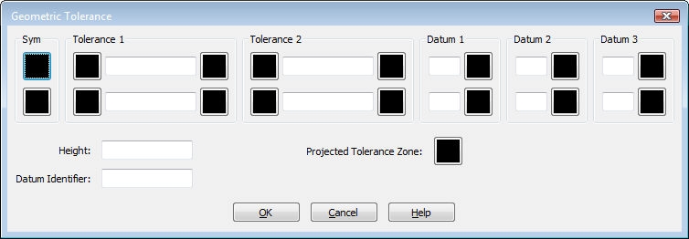
Select tolerance symbols and enter values, and then click OK.
Prompts you in the command bar:
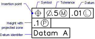
Select location for tolerance: (Specifies the insertion point for the tolerance symbol.)
Command Options
|
Option |
Description |
|
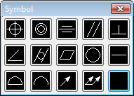
Inserts a tolerance symbol; displays dialog box:
Choose a symbol, and then click OK.
|
|
|
Tolerance 2 |
Specifies tolerance specification:
Diameter - toggles the diameter symbol when clicked. Value - specifies the tolerance value. Material condition - displays dialog box when clicked:
|
|
Datum 2 Datum 3 |
Specifies the datum reference:
Value - specifies the datum value. Material condition - click to display the Material Condition dialog box. |
|
Specifies the height of the tolerance symbols. |
|
|
Specifies datum indentifier, such as Datum A. |
|
|
Toggles the projected tolerance zone symbol:
|
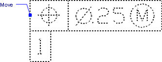
Grips Editing
Tolerances can be edited directly through grips:
Select the tolerance. Notice that it has one grip.
Drag the grip to move the tolerance.
Related Commands
Leader - attaches tolerances to leader lines.
DimOrdinate - draws x and y ordinate dimensions.
| Bricscad™ is commercialized by Bricsys NV. Bricsys NV and Vondle NV are fully owned subsidiaries of Menhirs NV. © 2001- Menhirs NV - All rights reserved. |