Works with Bricscad (Windows) Classic and Pro, Bricscad (Linux) Classic
Creates and modifies dimension styles, through the Drawing Explorer.
Accessing the Command
command bar: DimStyle
aliases: d, ddim, dimsty, ds, dst, expdimstyles, setdim
menu bar: Settings | Dimension Style
toolbar: Dimensions |
![]()
status bar: Standard (or name of other current dimension style)
: dimstyle
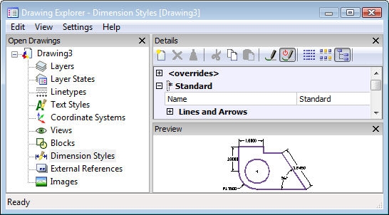
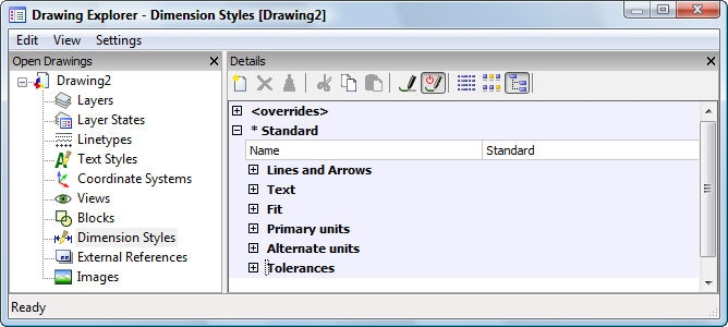
Displays the Drawing Explorer at the Dimension Styles section:
Create or edit dimension styles, and then click X.
Press F1 to access help.
<Overrides> - allows dimension settings to be overriden, without creating a new style.
*Standard - lists the dimension settings for the dimension style named "Standard"; the * asterisk indicates that this is the current style.
Command Options
|
Option |
Description |
|
Names of the dimension style; all styles can be renamed and deleted, except for the Standard style. |
|
|
Description |
|
Arrow 1 |
Specifies the style of arrowhead for the starting end of the dimension line; choose from one of the following types:
|
|
Arrow 2 |
Specifies the style of arrowhead for the other end of the dimension line. |
|
Arrow Size |
Specifies the length of the arrowhead; the width is scaled proportionately. |
|
Leader Arrow |
Specifies the style of arrowhead for the starting end of the leader line. |
|
Dim Line Color |
Specifies the color of the dimension line; choose from:
|
|
Dim Line type |
Specifies the line type of the dimension line; choose from any line type loaded into the current drawing. To access additional linetypes, click Load, and then choose one from the Load Linetypes dialog box. |
|
Dim Line LW |
Specifies the lineweight of the dimension line; choose from any lineweight supported by Bricscad. |
|
Dim Line Ext |
Specifies the distance that the dimension line extends beyond the extension lines. |
|
Dim Baseline Spacing |
Specifies the default distance between dimensions added with the DimBaseline command. |
|
Dim Line 1 |
Toggles the display of the first half of the dimension line (between the starting extension line and the text). |
|
Dim Line 2 |
Toggles the display of the second half of the dimension line (between the other extension line and the text). |
|
Ext Line Color |
Specifies the color of the dimension line; choose from:
|
|
Ext Line type |
Specifies the line type of both extension lines; choose from any line type loaded into the current drawing. To access additional linetypes, click Load, and then choose one from the Load Linetypes dialog box. |
|
Ext Line LW |
Specifies the lineweight of the extension line; choose from any lineweight supported by Bricscad. |
|
Ext Line Ext |
Specifies the distance that the extension lines extend beyond the dimension line. |
|
Ext Line Offset |
Specifies the offset distance between the object and the start of the extension lines. |
|
Ext Line 1 |
Toggles the display of the first extension line. |
|
Ext Line 2 |
Toggles the display of the second extension line. |
|
Ext line type 1 |
Specifies the line type of the first extension line; choose from any line type loaded into the current drawing. To access additional linetypes, click Load, and then choose one from the Load Linetypes dialog box. |
|
Ext line type 2 |
Specifies the line type of the second extension line; choose from any line type loaded into the current drawing. To access additional linetypes, click Load, and then choose one from the Load Linetypes dialog box. |
|
Ext line fixed length |
Specifies the length of fixed-length extension lines. |
|
Center Mark |
Specifies the type of center mark:
|
|
Center Mark Size |
Specifies the size of the center mark. |
|
Arc length symbol |
Specifies the location of the arc length symbol:
|
|
Jog angle |
Specifies the angle of the jog; default is 45 degrees. Enter another angle. |
|
Description
|
|
|
Text Style |
Specifies the style for dimension text; can use only styles created with the Style command. |
|
Text Color |
Specifies the color of the text; choose from:
|
|
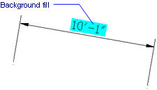
Text Fill |
Determines whether the dimension text has a rectangular background filled with color.
Choose from:
|
|
Text Fill Color |
Specifies the background fill color when Text Fill is set to Color. Choose a color from the drop list, or click Select Color to access the Select Color dialog box. |
|
Text Height |
Specifies the height of the text. |
|
Draw Frame Around Text |
Toggles a rectangle around the text. |
|
Text Pos Vert |
Justifies the text vertically relative to the dimension line:
|
|
Text Pos Hor |
Justifies the text horizontally relative to the extension lines:
|
|
Text Offset |
Specifies the size of gap between the dimension line and the text. |
|
Text Inside Align |
Justifies text when located between extension lines:
|
|
Text Outside Align |
Justifies text when located outside of the extension lines:
|
|
Description |
|
|
Arrow and Text Fit |
Specifies where text and arrows should be located when there is insufficient space for both between the extension lines:
|
|
Text Inside |
Toggles whether the text is forced between extension lines:
|
|
Dim Line Inside |
Toggles whether the dimension line is forced between extension lines:
|
|
Text Movement |
Specifies what happens when text is moved away from its default location:
|
|
Dim Scale Overall |
Specifies the overall scale factor for dimensions; this affects the size of arrows and text only. |
|
Place Text Manually |
Toggles whether the user must always specify the text location when creating dimensions. |
|
Dim Line Forced |
Forces the dimension line to be always drawn; forces leaders to be drawn with the DimDiameter and DimRadius commands. |
|
Description |
|
|
Dim Units |
Specifies the display units for dimensions:
|
|
Dim Precision |
Specifies the precision of units, either decimal places or fractional accuracy. |
|
Fractional Type |
Specifies how fractions are stacked:
|
|
Decimal Separator |
Specifies the character used to indicate the decimal point; can be any character. North American countries use the period; European countries use the comma. |
|
Dim Round |
Specifies the rounding of decimal numbers; range is none to 8 decimal places. |
|
Dim Prefix |
Specifies prefix text that appears in front of the dimension text, if any. |
|
Dim Suffix |
Specifies suffix text that appears after the dimension text, if any. |
|
Dim Scale Linear |
Specifies the multiplier for dimension values, such as 25.4 for changing inches to millimeters. |
|
Suppress Leading Zeros |
Toggles the display of zeros in front of the decimal point; for example, 0.23 is displayed as:
|
|
Suppress Trailing Zeros |
Toggles the display of zeros in front of the decimal point; for example, 1.2300 is displayed as:
|
|
Suppress Zero Feet |
Toggles the display of zero feet; for example, 0'-3" is displayed as:
|
|
Suppress Zero Inches |
Toggles the display of zero inches; for example, 1'-0" is displayed as:
|
|
Dim Angle Units |
Specifies the format of units in angular dimensions:
|
|
Dim Angle Precision |
Specifies the number of decimal places; ranges from 0 to 8. |
|
Suppress Angle Leading Zeros |
Toggles the display of zero degrees; for example, 0.1234 degrees is displayed as:
|
|
Suppress Angle Trailing Zeros |
Toggles the display of zeros after degrees; for example, 0.1200 degrees is displayed as:
|
|
Description |
|
|
Alternate Enabled |
Toggles the display of alternative units:
|
|
Alt Units |
Specifies the display units for dimensions:
|
|
Alt Precision |
Specifies the precision of units, either decimal places or fractional accuracy. |
|
Alt Scale Factor |
Specifies the multiplier for alternate values, such as 25.4 for showing millimeters (alternate units) next to inches (primary units). |
|
Alt Round |
Specifies the rounding of alternate numbers; range is none to 8 decimal places. |
|
Alt Prefix |
Specifies prefix text that appears in front of the alternate text, if any. |
|
Alt Suffix |
Specifies suffix text that appears in after the alternate text, if any. |
|
Alt Leading Zeros |
Toggles the display of zeros in front of the decimal point; for example, 0.23 is displayed as:
|
|
Alt Trailing Zeros |
Toggles the display of zeros in front of the decimal point; for example, 1.2300 is displayed as:
|
|
Alt Zero Feet |
Toggles the display of zero feet; for example, 0'-3" is displayed as:
|
|
Alt Zero Inches |
Toggles the display of zero inches; for example, 1'-0" is displayed as:
|
|
Description |
|
|
Tolerance Display |
Toggles the display of tolerance text. |
|
Tolerance Precision |
Specifies the display precision of tolerance text; range is 0 to 8 decimal places or 1/1 to 1/256 inch. |
|
Tolerance Limit Lower |
Specifies the value of the upper tolerance. |
|
Tolerance Limit Upper |
Specifies the value of the lower tolerance. |
|
Tolerance Text Height |
Specifies the height of tolerance text. |
|
Tolerance Pos Vert |
Locates the tolerance text relative to the dimension text:
|
|
Tolerance Suppress Leading Zeros |
Toggles the display of zeros in front of the decimal point. |
|
Tolerance Suppress Trailing Zeros |
Toggles the display of zeros behind the decimal point. |
|
Tolerance Suppress Zero Feet |
Toggles the display of zero feet. |
|
Tolerance Suppress Zero Inches |
Toggles the display of zero inches. |
|
Alt Tolerance Precision |
Specifies the number of decimal places for tolerances in alternate units. |
|
Alt Tolerance Suppress Leading Zeros |
Toggles the display of zeros in front of the decimal point. |
|
Alt Tolerance Suppress Trailing Zeros |
Toggles the display of zeros behind the decimal point. |
|
Alt Tolerance Suppress Zero Feet |
Toggles the display of zero feet. |
|
Alt Tolerance Suppress Zero Inches |
Toggles the display of zero inches. |
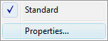
Right-click Standard (or other dimension style name) on the status bar for the shortcut menu:
![]()
|
Shortcut Menu |
Description |
|
Standard |
Chooses the default dimension style. When the drawing contains additional dimension styles, their names are listed here. |
|
Properties
|
Opens the Dimension Styles section of the Drawing Explorer.
|
| Bricscad™ is commercialized by Bricsys NV. Bricsys NV and Vondle NV are fully owned subsidiaries of Menhirs NV. Copyright © 2001- Menhirs NV - All rights reserved. |