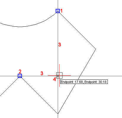
Entity Snap Tracking assists you to draw entities with respect to other entities.
When Entity Snap Tracking is turned on, Bricscad displays temporary alignments based on entity snap points. Entity Snap Tracking works in combination with Entity Snap tools. At least one Entity Snap mode must be on if you want to use Entity Snap Tracking.
Click the STRACK field in the Status bar to enable/disable Entity Snap Tracking.
Entity Snap Tracking alignments are parallel to the X- and Y-axis of the current UCS by default. If the Polar mode > 0x0002 setting is checked, the polar angles used in Polar Tracking (interval and additional angles) are also used in Entity Snap Tracking.
Alignment points must be acquired by moving the cursor over entity snap points. Acquired points display a small plus sign (+). To remove an acquired point, move the cursor back over the plus sign (+). If the Polar mode > 0x0008 is checked, you must press and hold the Shift key to acquire entity tracking points. Alignments relative to an acquired point are displayed as you move the cursor over their tracking paths. You can then define points either on the alignments or at the intersection of two alignments.
Using Entity Snap Tracking
Launch a drawing tool, e.g. Draw Line.
Hover the cursor over the first tracking point
(1).
A small plus sign (+) displays to indicate the tracking point is
active.
Hover the cursor over the second tracking point
(2)
A small plus sign (+) displays to indicate the tracking point is
active.
Move the cursor close to position 4.
Tracking lines display from both tracking points (3).
A cross marker (X) indicates the intersection of the tracking lines.
Snap markers display at the tracking points.
An Entity Snap Tracking tooltip at the intersection of the tracking lines shows the distances from the tracking points.

Click to accept the Entity Snap Tracking point.
| Bricscad™ is commercialized by Bricsys NV. Bricsys NV and Vondle NV are fully owned subsidiaries of Menhirs NV. Copyright © 2001- Menhirs NV - All rights reserved. |