Do one of the following:
Click the Chamfer tool button (![]() ) on the Chamfer/Fillet flyout
of the Modify toolbar.
) on the Chamfer/Fillet flyout
of the Modify toolbar.
Choose Chamfer in the Modify menu.
Type chamfer or CHA in the command bar, then press Enter.
Command: CHAMFER
The Chamfer command connects two non-parallel entities by extending or trimming them and then joining them with a line to create a beveled edge.
In Bricscad you can choose between two chamfer methods:
distance-distance: specify how far to trim the entities back from their intersection
distance-angle: specify the length of the chamfer and the angle it forms along the first entity.
The following entities can be chamfered: lines, polylines, rays and infinite lines. When chamfering a polyline, you can create a chamfer between two polyline segments or you can chamfer the entire polyline.
Chamfering using the distance-distance method
Do one of the following:
Click the Chamfer tool button (![]() ) on the Chamfer/Fillet flyout
of the Modify toolbar.
) on the Chamfer/Fillet flyout
of the Modify toolbar.
Choose Chamfer in the Modify menu.
Type chamfer or CHA in the command bar, then press Enter.
The command bar reads: Chamfer (<current chamfer settings>): Settings/Polyline/Angle/Distance/mEthod/Trim/Undo/Multiple/<Select first entity>:
A prompt menu displays:
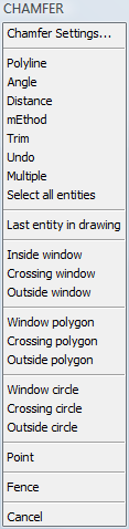
(option) Choose Chamfer
Settings ... in the prompt menu or type S and press Enter.
In the Settings dialog window:
Specify the Chamfer first distance.
Set the Chamfer second distance.
Set the Chamfer mode to Distance-Distance.
Close the Settings
dialog window.
The command bar reads: Chamfer (<current chamfer settings>):
Settings/Polyline/Angle/Distance/mEthod/Trim/Undo/Multiple/<Select
first entity>:
Select the first entity or polyline segment.
The command window reads: Select second entity.
Select the second entity or polyline segment.
The chamfer is created.
Chamfering using the length-angle method
Do one of the following:
Click the Chamfer tool button (![]() ) on the Chamfer/Fillet flyout
of the Modify toolbar.
) on the Chamfer/Fillet flyout
of the Modify toolbar.
Choose Chamfer in the Modify menu.
Type chamfer or CHA in the command bar, then press Enter.
The command bar reads: Chamfer (<current chamfer settings>): Settings/Polyline/<Select first entity>:
A prompt menu displays.
Choose Chamfer Settings ... in the prompt menu or type S and press Enter.
In the Settings dialog window:
Specify the Chamfer length.
Set the Chamfer angle.
Set the Chamfer mode to Length-Angle.
Close the Settings dialog window.
The command bar reads: Chamfer (<current chamfer settings>):
Settings/Polyline/<Select first entity>:
Select the first entity or polyline segment.
The command window reads: Select second entity.
Select the second entity or polyline segment.
The chamfer is created.
Chamfering all vertices of a polyline
Do one of the following:
Click the Chamfer tool button (![]() ) on the Chamfer/Fillet flyout
of the Modify toolbar.
) on the Chamfer/Fillet flyout
of the Modify toolbar.
Choose Chamfer in the Modify menu.
Type chamfer or CHA in the command bar, then press Enter.
The command bar reads: Chamfer (<current chamfer settings>): Settings/Polyline/<Select first entity>:
A prompt menu displays:
(option) Adjust the Chamfer Settings.
Choose Polyline in
the prompt menu or type P and press
Enter.
The command bar reads: Select 2D polyline to chamfer:
Select a polyline.
All vertices of the selected polyline are chamfered.
|
NOTE |
When the chamfer method is distance-angle, the direction of the polyline defines which is the first entity of a vertex. See drawing rectangles for more information about the direction of closed polylines. |
| © Menhirs NV. All rights reserved. |