PlotterManager
Works with Bricscad (Windows) Classic, Pro and
Platinum, Bricscad (Linux) Classic, Pro and Platinum
Creates customized parameter PC3 files for printers and other
output devices; executes the PlotConfig.exe utility program.
Accessing the Command
command bar: plottermanager
menu bar: File | Plotter
Manager
: plottermanager
Displays a window:
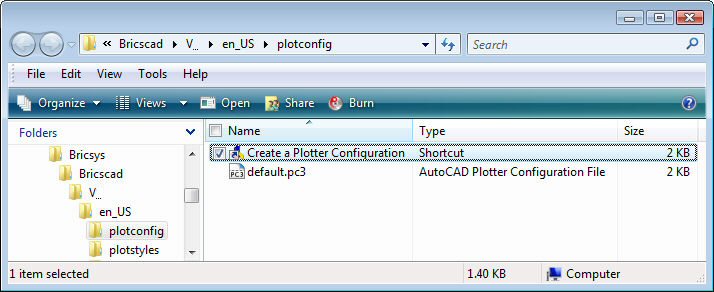
To edit an existing plotter configuration file,
double click a PC3 file, such as default.pc3.
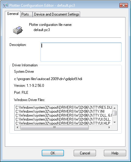
Make changes the properties, and then click
OK.
To create a new plotter configuration file,
double-click the Create a Plotter
Configuration shortcut.
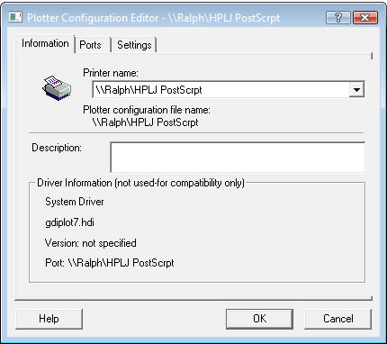
Select the properties, and then click OK.
You are prompted to name the new plotter
configuration file:
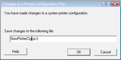
Enter a name, and then click OK.
The new PC3 file is added to the
C:\Users\<loginname>\AppData\Roaming\Bricsys\Bricscad\V...\en_US\plotconfig
folder.
Command Options
|
General Option
|
Description
|
|
Description
|
Describes the plotter configuration; displayed
in tooltips.
This field is optional.
|
|
|
|
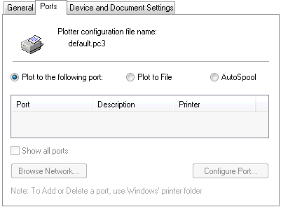
Ports Option
|
|
|
Plot
to the following port
|
Plots drawings to the printer attached to the
specified port.
|
|
Plot to file
|
Plots drawings to PLT files. These plot files
can be read by other software programs.
|
|
AutoSpool
|
Sends drawings to spoolers, which control how
and when drawings are plotted. The spooler software must be set up
separately.
|
|
Show all ports
|
Displays the names of all local and network
ports found on the current computer.
|
|
Browse Network
|
Opens the Browse Network window. Allows you to
locate printers attached to the network.
|
|
Configure Port
|
Opens the Configure Port dialog box. Allows you
to configure the selected port.
|
|
|
|
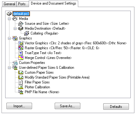
Device and Document
Settings Option
|
|
|
Media
|
Specifies settings for the media (paper).
|
|
|
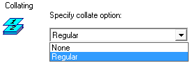
Specifies how to collate pages:
None - does not collate; drawings are printed
normally.
Regular - prints layouts of each drawing
together.
This option is useful when printing multiple
copies of drawings with multiple layouts.
|
|
|
|
Graphics
|
Specifies how graphics are handled by the
printer.
|
|
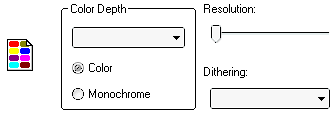
Vector Graphics
(currently NOT supported)
|
Specifies how vector graphics are handled:
Color depth - specifies the number of colors to
use.
Color - outputs the drawing in color.
Monochrome - outputs the drawing in monochrome
(black).
Resolution - adjusts the resolution; lower resolution
is coarser, but prints more quickly.
Dithering - specifies the type of dithering, which
simulates more colors at the cost of lower resolution.
Vector graphics are normal Bricscad drawings
made with lines, arcs, and so on.
|
|
|
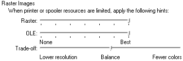
Specifies how raster vectors are handled:
Raster - adjusts how raster images are handled.
OLE - adjust how OLE objects are printed; ranges
from:
Trade-off - specifies how Bricscad should handle
drawings with very large raster images that take up much
memory:
-
Lower Resolution -
prints images with lower resolution but full colors; suitable for
photographs.
-
Balance - prints
images with as many colors and as much resolution as possible.
-
Fewer Colors - prints
images with fewer colors but full resolution; suitable for
grayscale images.
Raster graphics are images attached to
drawings.
|
|
|
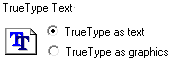
Specifies how TrueType text is handled:
|
|
|
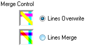
Specifies how overlapping lines are merged:
-
Lines Overwrite -
specifies that entities with higher draw order overwrite other
entities.
-
Lines Merge -
specifies that entities are blended to merge their colors; allows
entities with lower draw order to be seen.
|
|
|
|
Custom
Properties

|
Accesses the Custom Properties dialog box.
This dialog box lists properties unique to the
selected output device.
Its content varies according the capabilities
of the device.
Custom properties are not supported on the
Linux platform.
|
|
|
|
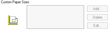
User-Defined Paper
Sizes & Calibration
|
|
|
|
Specifies custom paper sizes.
Add - adds user-defined paper sizes.
Delete - removes custom paper sizes.
Edit - edits custom paper sizes.
|
|
|
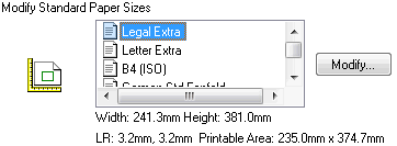
Modifies the margins on standard paper
sizes:
Modify - displays the Custom Paper Size - Printable
Area wizard. See below.
|
|
|
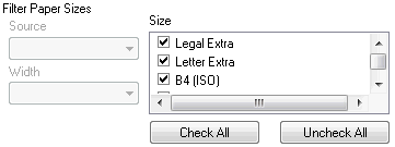
Reduces the number of paper sizes. The list of
paper sizes normally shows all sizes that the output device is
capable of handling. In reality, you work with just a few
sizes.
Click checkboxes next to sizes you don't want
displayed by the Print dialog box.
Check All - includes all paper sizes.
Uncheck All - excludes all paper sizes.
|
|
Plotter Calibration
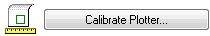
|
Calibrates the plotter.
Calibrate Plotter -
displays the Calibrate Plotter wizard. See below.
This option was necessary in the days of pen plotters, which
could go out of alignment; today's inkjet and laser printers not to
have the problem.
|
|
PMP File Name
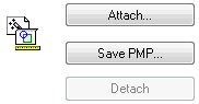
|
Specifies PMP file names.
PMP is short for "plot model parameter." These files stored
custom paper sizes and plotter calibration data; they are
associated with PC3 plotter configuration files.
Attach - displays the
Open dialog box; choose a PMP file, and then click Open.
Save PMP - displays the
Save As dialog box; name the file, and then click Save.
Detach - removes the
attached PMP file.
|
|
|
|
Import
|
Imports PCP and PC2 files; displays the Plotting Components
dialog box.
-
Click OK.
-
Displays the Import dialog box.
-
Choose a PCP or PC2 file, and then click Import.
PCP and PC2 are older formats of the plotter configuration
files.
|
|
Save As
|
Displays the Save As dialog box; saves settings as PC3
files.
-
Enter a file name, and then click Save.
PC3 is short for "plotter configuration version 3"; these files
store parameters for specific plotters.
You can have multiple PC3 files for each plotter or printer.
|
|
Defaults
|
Resets all options to their default values; prompts you:
Do you want to set everything to defaults?
- type Y or N.
|
Related Commands
ConvertCtb -
converts CTB plot style files to STB files.
ConvertPStyles - converts drawings
from CTB to STB plot styles.
PageSetup - assigns
plot style to drawings.
PlotStyle - sets the
current plot style.
Print and Plot -
plot drawings.
StylesManager - creates and
attaches plot styles to drawings.
|
© Menhirs NV. All rights reserved. |