THICKNESS = 0 (left), THICKNESS = 50 (middle), ELEVATION = 50 (right)
Commands: PLINE, BOUNDARY and -BOUNDARY
A polyline is an open or closed sequence of connected line and/or arc segments, which are treated as a single entity. Each segment of a polyline can have a width that is either constant or tapers over the length of the segment.
The Pline command interactively creates open and closed polylines entering points.
The Boundary and - Boundary commands create closed polylines from an enclosed area, defined by other entities.
The THICKNESS system variable specifies the height of a polyline. If THICKNESS = 0 (zero) there is no visual difference between polylines and a series of lines and/or arcs.
|
|
|
THICKNESS = 0 (left), THICKNESS = 50 (middle), ELEVATION = 50 (right) |
When a polyline is edited, you can modify the entire polyline or change individual segments and you can add or remove vertices.
|
|
|
|
zero width polyline |
constant width polyline |
|
|
|
|
tapered width polyline |
|
|
NOTE |
When Fill Mode is turned OFF, all filled entities, such as wide polylines and planes, display and print as outlines. |
Do one of the following
Click the Polyline tool button (![]() ) on the Draw toolbar.
) on the Draw toolbar.
Choose Polyline in the Draw menu.
Type pline in the command bar, then press Enter.
Type PL in the command bar, then press Enter.
The command bar reads: ENTER to use last point/Follow/<Start of polyline>:
A prompt menu displays:
![]()
Specify the start point of the polyline.
The prompt menu changes:
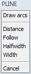
Specify the second point of the polyline.
The prompt menu changes:
(option) Repeat step 3 to add more straight segments.
(option) Do one of the following to start drawing arc segments:
Type A, then press Enter.
Choose Draw arcs in the prompt menu.
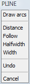
The prompt menu changes:
An arc segment displays dynamically. The arc is tangent to the previous line segment.
Specify the endpoint of the arc.
(option) Repeat step 6 to add more arc segments.
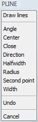
(option) Do one of the following to start drawing line segments:
Type L, then press Enter.
Choose Draw lines in the prompt menu.
Specify the endpoint of the line segment.
Right click or choose Done in the prompt menu to stop.
(option) Right click to restart.
Do one of the following
Click the Boundary
Polyline tool button (![]() ) on the Draw 2D toolbar.
) on the Draw 2D toolbar.
Choose Boundary Polyline in the Draw menu.
Type boundary in the command bar, then press Enter.
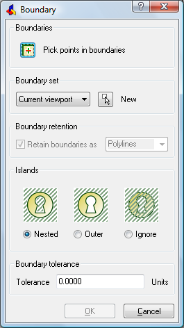
The Boundary dialog box opens.
(option) Click the New
Boundary Set button (![]() )
)
The Boundary dialog closes.
Select the boundary entities in the drawing, then Press Enter.
The Boundary dialog opens.
Click the Pick points in
boundaries (![]() ) button on the Boundary dialog box.
) button on the Boundary dialog box.
The dialog box closes.
Click in the area where you want to create the
boundary polyline: point 1 in the image below.
The boundary polyline displays in dashed lines.
(option) Keep picking points to create more boundary polylines.
Right click to accept the polyline(s).
The Boundary dialog box opens
again.
Click the OK button
on the Boundary dialog box.
The polyline(s) is (are) created.
|
NOTES |
|
| © Menhirs NV. All rights reserved. |