Do one of the following:
Click the Edit
Polyline tool button (![]() ) on the Modify toolbar.
) on the Modify toolbar.
Choose Edit Polyline in the Modify menu.
Type editpline or pedit in the command window, then press Enter.
Command: PEDIT
The Edit vertices option of the Edit Polyline tool modifies individual polyline vertices.
When you select this option, the program switches into a special vertex editing mode and places an X on the first vertex. The X indicates the vertex you are editing. The Next and Previous options move the X to the next or previous vertex. You can edit only one vertex at a time.
When editing vertices, you can modify the polyline in the following ways:
Starting the polyline vertex editing mode
Do one of the following:
Click the Edit
Polyline tool button (![]() ) on the Modify toolbar.
) on the Modify toolbar.
Choose Edit Polyline in the Modify menu.
Type editpline or pedit in the command window, then press Enter.
The command bar reads: Select polyline to edit.
Select the polyline.
The command bar reads: Edit polyline: Edit vertices/Close (or
Open)/Decurve/Fit/Join/Linetype-Mode/Reverse/Spline/Taper/Width/Undo/<eXit>:
A prompt menu displays.
Choose Edit vertices
in the prompt menu or type E and
press Enter.
The command bar reads:
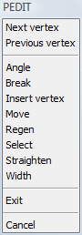
Next/Previous/Angle/Break/Insert/Move/Regen/SElect/Straighten/Width/eXit/<Next>:
The Editpline prompt menu
changes:
A triangle indicates the start point of the polyline. The first vertex of the polyline is selected.
Convert a straight polyline segment into a curve
Start the polyline vertex editing mode.
Select the start vertex of the segment you want to
convert.
Choose Next vertex / Previous vertex in the prompt menu to
select a vertex.
The X indicates the currently
selected vertex.
Choose Angle in the
prompt menu or type A and press
Enter.
The prompt menu closes.
The command bar reads: Included angle for segment (>0 is ccw, 0
is straight, <0 is cw) <current angle>:
Type a new included angle for the segment and press
Enter.
The direction of an arc segment is as follows:
positive angles: counter clockwise
negative angle: clockwise direction
0° for straight segments
Choose Exit in the prompt menu or type X and press Enter to leave the Polyline vertex editing mode.
Do one of the following:
Continue editing the selected polyline.
Choose Exit in the prompt menu or press Enter to conclude the Edit Polyline tool.
Break a polyline into two separate polylines.
Start the polyline vertex editing mode.
Select the start vertex where you want to break the
polyline.
Choose Next vertex / Previous vertex in the prompt menu to
select a vertex.
The X indicates the currently
selected vertex.
Choose Break in the prompt menu or type B and press Enter.
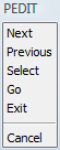
The command bar reads: Next/Previous/Select/Go/eXit/<Next>:
The prompt menu changes:
(option) Do one of the following to select a second vertex:
Choose Next vertex / Previous vertex in the prompt menu.
Choose Select
in the prompt menu or type S and
press Enter.
You are prompted to select a vertex.
Choose Go in the
prompt menu or type G and press
Enter.
The polyline s broken into two polylines.
If a second point is selected in step 4 the segment(s) between the
selected vertices is (are) deleted.
Choose Exit in the prompt menu or type X and press Enter to leave the Polyline vertex editing mode.
Do one of the following:
Continue editing the selected polyline.
Choose Exit in the prompt menu or press Enter to conclude the Edit Polyline tool.
Insert a new vertex in a polyline
Start the polyline vertex editing mode.
Select the start vertex of the segment where you
want to insert a vertex.
Choose Next vertex / Previous vertex in the prompt menu to
select a vertex.
The X indicates the currently
selected vertex.
Choose Insert vertex
in the prompt menu or type I and
press Enter.
The command bar reads: Location for new vertex:
Specify the location for the new vertex.
The new vertex is inserted.
Choose Exit in the prompt menu or type X and press Enter to leave the Polyline vertex editing mode.
Do one of the following:
Continue editing the selected polyline.
Choose Exit in the prompt menu or press Enter to conclude the Edit Polyline tool.
Start the polyline vertex editing mode.
Select the vertex you want to move.
Choose Next vertex / Previous vertex in the prompt menu to
select a vertex.
The X indicates the currently
selected vertex.
Choose Move in the
prompt menu or type M and press
Enter.
The command bar reads: New location for vertex.
Specify the new location for the selected
vertex.
The vertex is moved.
Choose Exit in the prompt menu or type X and press Enter to leave the Polyline vertex editing mode.
Do one of the following:
Continue editing the selected polyline.
Choose Exit in the prompt menu or press Enter to conclude the Edit Polyline tool.
Start the polyline vertex editing mode.
Select the vertex before the first vertex you want
to delete.
Choose Next vertex / Previous vertex in the prompt menu to
select a vertex.
The X indicates the currently
selected vertex.
Choose Straighten in
the prompt menu or type S and press
Enter.
The command bar reads: Straighten:
Next/Previous/Select/Go/eXit/<Next>:
Do one of the following to select the vertex after the last vertex you want to delete:
Choose Next vertex / Previous vertex in the prompt menu.
Choose Select
in the prompt menu or type S and
press Enter.
You are prompted to select a vertex.
Choose Go in the
prompt menu or type G and press
Enter.
The vertices between the selected vertices are removed.
A straight segment is drawn between the selected vertices.
Choose Exit in the prompt menu or type X and press Enter to leave the Polyline vertex editing mode.
Do one of the following:
Continue editing the selected polyline.
Choose Exit in the prompt menu or press Enter to conclude the Edit Polyline tool.
Change the width of a polyline segment
Start the polyline vertex editing mode.
Select the start vertex of the segment you want to
change the width of.
Choose Next vertex / Previous vertex in the prompt menu to
select a vertex.
The X indicates the currently
selected vertex.
Enter starting width <current width>:
Do one of the following:
Type the new width in the command bar and press Enter.
Click to define the width graphically.
The command bar reads: Enter ending width <current width>:
Do one of the following:
Type the new width in the command bar and press Enter.
Click to define the width graphically.
Choose Exit in the prompt menu or type X and press Enter to leave the Polyline vertex editing mode.
Do one of the following:
Continue editing the selected polyline.
Choose Exit in the prompt menu or press Enter to conclude the Edit Polyline tool.
|
NOTE |
The new width is applied when you conclude the Edit Polyline tool in step 6. |
| © Menhirs NV. All rights reserved. |