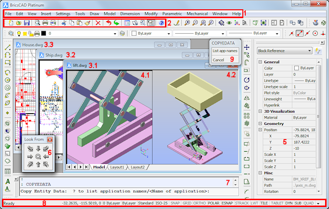
The layout of the BricsCAD application window can be fully customized.
You can:
Menu Bar
Toolbar (docked)
Drawing windows
Drawing viewports
Properties Bar
Toolbar (floating)
Command bar
Status Bar
Prompt Menu
Do one of the following:
Choose Command Bar in the View Menu.
Move the cursor to a docked toolbar, then right click and choose Command Bar in the context menu.
Double click the Status field at the left hand side of the Status Bar.
The Command Window closes if it was open and vice versa.
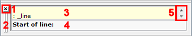
Close button
Press and hold the left mouse button to move the command bar
Command History List field: the content of the history list field can be copied to the command edit field.
Command Edit field
If the Enable flag of the AUTOCOMPLETEMODE
system variable is set, command entries are completed
automatically.
Do one of the following:
Press Enter if the currently completed command displays.
Choose a command in the Suggestion list.
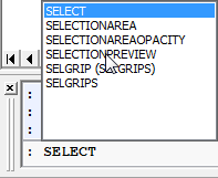
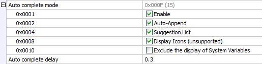
Autocomplete options are:
Command history scroll buttons
|
NOTES |
|
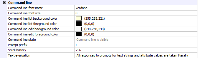
To set the command line properties
Open the Settings window.
Go to Program Options / User
Preferences / Command Line.
Do one of the following:
Choose Status Bar in the View Menu.
Press the Shift + F3 keyboard shortcut.
The Status Bar closes if it was open and vice versa.

The Status Bar fields are:
Status:
displays the status of the software.
when the cursor is in a menu or on a toolbar: gives a brief description of the tool or menu item.
when the command window is closed: displays the tool options and keyboard entry.
double click to open/close the Command Bar.
Coordinates: displays the coordinates of the current cursor position (depending on the setting of the COORDS variable).
Right click, then choose Off, Relative or Absolute in the context menu.
Click to cycle the Coordinate setting. The sequence is Off, Relative, Absolute.
Layer: displays the name of the current layer.
click to open the Layer Explorer.
right click to select the current layer
Color: displays the current color.
click to open the Select Color dialog window.
right click to select one of the basic colors.
Linetype: displays the name of the current linetype.
click to open the Linetype Explorer.
right click to select the current linetype
Text Style: displays the name of the current text style.
click to open the Styles Explorer.
right click to select the current text style.
Dimension Style: displays the name of the current dimension style
click to open the Dimensions Settings dialog window.
right click to select the current dimension style.
Snap:
click to toggle Snap on (![]() ) /off (
) /off (![]() ).
).
right click, then choose Settings to edit the Snap and Grid settings.
Grid: click to toggle the display of grid points on (![]() ) / off (
) / off (![]() ) in the current viewport.
) in the current viewport.
Orthogonal Mode: click to toggle Orthogonal mode on (![]() ) /off (
) /off (![]() ).
).
Turning Orthogonal mode on
automatically disables Polar
Tracking.
Polar Tracking (AutoSnap):
click to toggle Polar
Tracking on (![]() ) / off (
) / off (![]() ).
).
Turning Polar Tracking on
automatically disables Orthogonal
mode.
right click, then choose Settings to edit the Polar Tracking settings.
Entity Snaps:
click to toggle Entity
Snaps on (![]() ) / off (
) / off (![]() ).
).
right click, then choose Settings to edit the Entity Snaps settings.
Snap Tracking (AutoSnap):
click to toggle Snap
Tracking on (![]() ) /off (
) /off (![]() ).
).
right click, then choose Settings to edit the Snap Tracking settings.
Line Weight Display:
click to toggle the display of Line Weights On (![]() ) or Off (
) or Off (![]() ).
).
right click, then choose On or Off to control the display of Line Weights.
Current Workspace.
Tile : Model space with tiled viewports.
M:Layout : Model space with floating viewports
P:Layout :
Paper space
Right click the Workspace field, then choose a layout to open.

Tablet: Initializes the use of a drawing
tablet.
Dynamic UCS: click to toggle the
Dynamic UCS feature ON (![]() ) or Off (
) or Off (![]() ).
).
Dynamic Dimensions:
click to toggle the display of Dynamic Dimensions On (![]() ) or Off (
) or Off (![]() ).
).
right click, then choose Settings to edit the Dynamic Dimensions settings.
Subentity Selection:
click to toggle the Subentity Selection On (![]() )or Off (
)or Off (![]() ).
).
right click, then choose Settings to edit the Subentity Selection settings.
Quad Display:
click to toggle the display of the
Quad On (![]() ) or Off (
) or Off (![]() ).
).
right click, then choose Settings to edit the Quad settings.
|
NOTE |
Orthogonal mode (field 10) is switched off if Polar Tracking (field 11) is on and vice versa. |
Click the down arrow
button (![]() ) at the right end of the
status bar.
) at the right end of the
status bar.
The status options display.
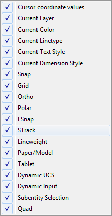
Do one of the following:
Click an unmarked field name to add it to the status bar.
Click a marked field name to remove it from the status bar.
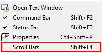
To toggle scroll bars on / off:
(option) Hold down the Shift key, then press the F4 function key.
(option) Choose Scroll
Bars in the View menu.
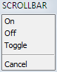
(option) Type scrollbar in the command bar, then do one of the following:
type off in the command bar or choose Off in the context menu.
type on in the command bar or choose On in the context menu.
type T in the command bar or choose Toggle in the context menu.
| © Menhirs NV. All rights reserved. |