Commands: RTROT, RTROTCTR, RTROTF, RTROTX, RTROTY, RTROTZ, DDVPOINT, -VIEW, PLAN and VPOINT
The Rtrot (Real-Time Constrained Sphere) command rotates 3D drawings in real-time.
The Rtrotctr (Real-time Sphere Center) command freely rotates 3D drawings in real-time about a user-defined center point.
The Rtrotf (Real-time Free Sphere) command freely rotates 3D drawings in real-time.
The Rtrotx , Rtroty and Rtrotz commands rotates 3D drawings in real-time about the x, y or z screen axis.
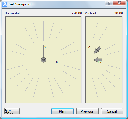
The Ddvpoint command sets 3D viewpoints or plan view, through a dialog box (short for "dynamic dialog view point").
The Plan command displays the plan viewpoint of drawings.
The Vpoint command changes the 3D viewpoint.
In order to view your 3D drawings from any angle, you can rotate a view. The Real-Time Motion tools of BricsCAD allow you to rotate a view in real-time. You can rotate the view about the X, Y or Z screen axis or in any direction (real-time sphere). If the Continuous Motion variable is set, the view rotation continues until you conclude the Real-Time Motion command.
See also: View manipulation using the mouse.
|
NOTE |
'Real-time' commands should not be used when drawing in 2D. Use the Plan View tool to restore top view. |
Restoring orthographic and isometric views
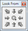
The tools on the Look From toolbar allow to restore orthographic and isometric views using the -VIEW command options.
The middle tool button allows to choose between Top (![]() ) and Bottom
(
) and Bottom
(![]() ) view: Press and hold the left
mouse button, then choose the appropriate button.
) view: Press and hold the left
mouse button, then choose the appropriate button.
|
NOTE |
If the UCSORTHO system variable is ON the related orthographic UCS is restored automatically. |
Do one of the following:
Click the Real-Time
Constrained Sphere tool button (![]() )
)
or the Real-Time Sphere tool button
(![]() ) on the Real-Time Motion toolbar.
) on the Real-Time Motion toolbar.
Choose Real-Time
Motion > Real-Time Constrained
Sphere
or Real-Time Motion > Real-Time Sphere in the View menu.
Type rtrot , rtrotf or rtrotctr in the command bar, then press Enter.
The command bar reads: >> Press ENTER or Esc to complete, or right click to display context menu ...
Press and hold the left mouse button.
Move the mouse to rotate the view.
Using the Real-Time Constrained Sphere command horizontal mouse movement (parallel to the screen X-axis) rotates the 3D model about the world Z-axis.
Using the Real-time Sphere Center command you are prompted to specify a center point for the rotation first.
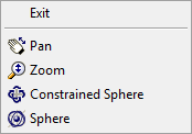
(option) Right click to display a context menu:
To abort the Real-Time Sphere commands, do one of the following:
Right click, then choose Exit in the context menu..
Press Enter, space bar or Esc.
Rotating a view about the view X-axis
Do one of the following:
Click the Real-Time
X tool button (![]() ) on the Real-Time Motion toolbar.
) on the Real-Time Motion toolbar.
Choose Real-Time Motion > Real-Time X in the View menu.
Type rtrotx in the command bar, then press Enter.
The command bar reads: >> Press ENTER or Esc to complete, or right click to display context menu ...
Press and hold the left mouse button.
Move the mouse to rotate the view.
(option) Right click to display a context menu:
To abort the Real-Time X command, do one of the following:
Right click.
Press Enter, space bar or Esc.
Rotating a view about the view Y-axis
Do one of the following:
Click the Real-Time
Y tool button (![]() ) on the Real-Time Motion toolbar.
) on the Real-Time Motion toolbar.
Choose Real-Time Motion > Real-Time Y in the View menu.
Type rtroty in the command bar, then press Enter.
The command bar reads: >> Press ENTER or Esc to complete, or right click to display context menu ...
Press and hold the left mouse button.
Move the mouse to rotate the view.
(option) Right click to display a context menu:
To abort the Real-Time Y command, do one of the following:
Right click.
Press Enter, space bar or Esc.
Rotating a view about the view Z-axis
Do one of the following:
Click the Real-Time
Z tool button (![]() ) on the Real-Time Motion toolbar.
) on the Real-Time Motion toolbar.
Choose Real-Time Motion > Real-Time Z in the View menu.
Type rtrotz in the command bar, then press Enter.
The command bar reads: >> Press ENTER or Esc to complete, or right click to display context menu ...
Press and hold the left mouse button.
Move the mouse to rotate the view.
(option) Right click to display a context menu:
To abort the Real-Time Z command, do one of the following:
Right click.
Press Enter, space bar or Esc.
Do one of the following:
Click the Set
Viewpoint ... tool button (![]() ) on the View toolbar.
) on the View toolbar.
Choose Set Viewpoint ... in the View menu.
Type ddvpoint in the command bar, then press Enter.
The Preset Viewpoint dialog opens.
Click the Angle
Precision button (![]() ) to choose a different display
mode for the Set Viewpoint
dialog.
) to choose a different display
mode for the Set Viewpoint
dialog.
Then choose either 45°, 15° or 5°.
|
|
|
45° display mode |
In 15° or
5° mode
click in the inner area of the Horizontal and Vertical fields to choose a 45° display mode viewpoint.
Click in the outer area of the Horizontal and Vertical fields to choose another angle.
To set the Vertical view angle, do one of the following:
Skip this step to accept the default vertical view directions:
Horizontal for East, North, West and South.
Downwards for the other directions.
If both the down- and left-arrow show in the Vertical field, the default vertical view directions are active.
Select a 45°
mode angle in the inner area, then click to confirm your
choice.
A single arrow indicates the selected vertical view direction.
If in 15° or
5° mode
in, select a view direction in the outer area, then click to
confirm your choice.
The selected angle displays in bold.
The view is updated as you click.
To set the Horizontal view angle, do one of the following:
Select a 45°
mode angle in the inner area, then click to confirm your
choice.
An arrow indicates the selected horizontal view direction.
The perspective of the arrow reflects the vertical view
direction.
If in 15° or
5° mode
in, select a view direction in the outer area, then click to
confirm your choice.
The selected angle displays in bold.
The view is updated as you click.
|
NOTE |
Use the Isometric Views toolbar for standard view rotations: top, front, back, left, right and isometric views. |
Do one of the following:
Click the Plan
View tool button (![]() ) on the View toolbar.
) on the View toolbar.
Choose Plan View in the View menu.
Type plan in the command bar, then press Enter.
The command bar reads: Plan view of: UCS/World/<current UCS>:
A prompt menu opens:
Press Enter to restore the plan view with respect to the current coordinate system.
|
NOTES |
|
| © Menhirs NV. All rights reserved. |