![]() Watch the movie about Kinematic
Analysis on the Bricsys channel on
YouTube.
Watch the movie about Kinematic
Analysis on the Bricsys channel on
YouTube.
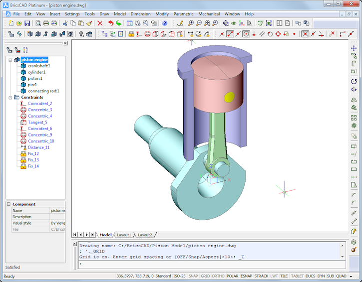
The source files for this tutorial are installed in the [BricsCAD Installation folder]\Samples\Mechanical\piston folder.
Assembly design is a typical application where constraints are commonly used. Since V13, BricsCAD Platinum allows users to assemble mechanisms and run kinematic analysis.
This tutorial shows you how to start working with assemblies in BricsCAD. You will learn how to assemble the different parts in a 3D model, which lets you control the final result.
There are two approaches in MCAD (Mechanical Computer-Aided Design) to build an assembly: top-down and bottom-up.
In the top-down approach, you start with an empty assembly and the geometry of each component is then created, one by one, in the assembly.
In the bottom-up approach, each component is first created as a single entity. All components are then inserted into the assembly. The position of each component is controlled through 3D constraints.
We will now assemble a simplified - in comparison with a real-world engine - model of a piston engine.
Step 1: Preparing for the exercise
You need a BricsCAD Platinum license for this tutorial.
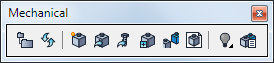
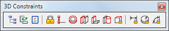
Make sure the Mechanical and 3D
Constraints toolbars are open.
To open a toolbar: move the cursor over an open toolbar, then right
click and select the required toolbars from the toolbar list.
Toolbars that are already open are marked in the list.
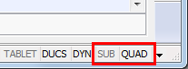
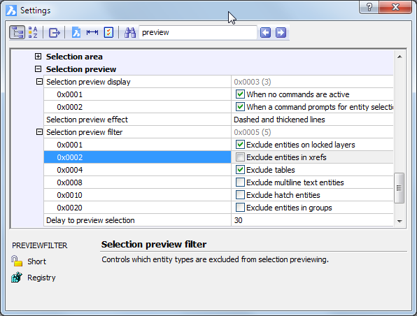
Make sure that the Quad cursor menu is active and that Subentity Selection is switched off.
Make sure that the Exclude
entities in Xrefs option of the PREVIEWFILTER
system variable is switched off.
Open the Mechanical
Browser dialog box.
Do one of the following:
Click the Mechanical
Browser tool button (![]() ) on the Mechanical toolbar.
) on the Mechanical toolbar.
Choose Mechanical Browser in the Mechanical menu.
Type bmbrowser in the command bar.
![]()
Step 2: Creating the assembly drawing
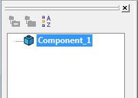
Click the New
Component tool button (![]() ) on the Mechanical toolbar.
) on the Mechanical toolbar.
A new drawing of the name Component_1.dwg is created and Component_1 is added in the Mechanical Browser.
In the bottom part of the Mechanical Browser, click the Name field and rename the main component: Piston Engine.
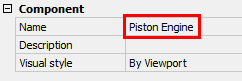
The drawing name automatically matches the main component name.
Save the drawing.
Click the Insert
Component tool button (![]() ) on the Mechanical toolbar.
) on the Mechanical toolbar.
The Insert Mechanical Component
dialog displays:
Open the [BricsCAD Installation
folder]\Samples\Mechanical\piston folder.
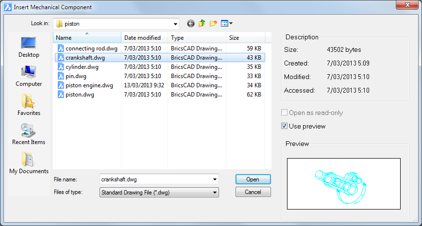
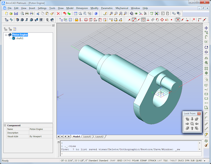
Select the crankshaft.dwg, then double click or click the
Open button.
The component is attached to the cursor with its origin point.
Dynamic dimensions display: Distance from the origin of the current
coordinate system and angle from the X-axis.
We will consider the crankshaft as the anchor
component of the assembly, and therefore insert it at the
origin (0,0,0).
Please make sure the insertion point is exactly at 0,0,0, otherwise
the kinematic analysis in step 6 might fail.
Use the tools on the Look From toolbar to adjust the view orientation.
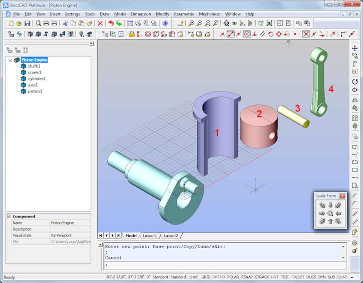
Repeat the previous steps to insert the other components: cylinder (1), piston (2), pin (3) and connecting rod (4).
Step 4: Positioning the components
Click the Fix tool
button (![]() ) on the 3D Constraints toolbar.
) on the 3D Constraints toolbar.
The command bar reads: Select an edge, face or 3D solid:
Move the cursor over the crankshaft, then do one of the following:
Hit the TAB key until the whole solid is selected.
Press and hold the Shift key, then hit the TAB key.
The position of the crankshaft is now locked, as indicated in the Constraints tree in the Mechanical Browser.
![]()
Clicking the constraint highlights the solid, face or edge it applies to.
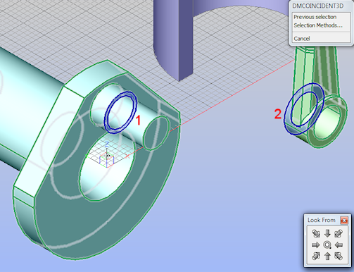
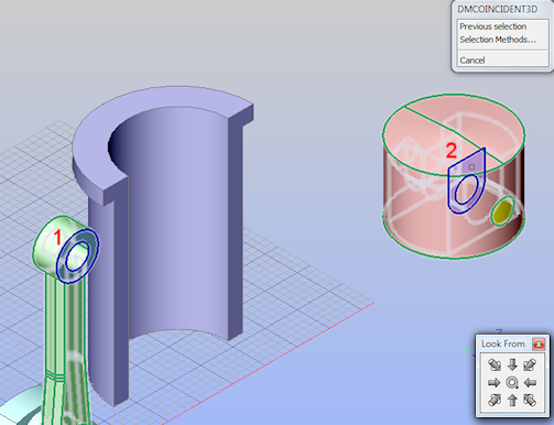
Click the Coincident
tool button (![]() ) on the 3D Constraints toolbar.
) on the 3D Constraints toolbar.
The command bar reads: Select a pair of subentities:
Move the cursor over two planar faces of the
crankshaft (1) and the connecting rod (2) as indicated in the image
below.
Hit the TAB key until the correct face highlights, then click and
move the cursor to the second face.
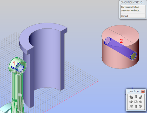
Click the Concentric
tool button (![]() ) on the 3D Constraints toolbar.
) on the 3D Constraints toolbar.
The command bar reads: Select a pair of subentities:
Move the cursor over two cylindrical faces of the
crankshaft (1) and the connecting rod (2) as indicated in the image
below.
Hit the TAB key until the correct face highlights, then click and
move the cursor to the second face.
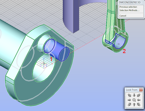
The connecting rod is automatically moved to the right position according to our design intent.
Click the Concentric
tool button (![]() ) on the 3D Constraints toolbar.
) on the 3D Constraints toolbar.
The command bar reads: Select a pair of subentities:
Move the cursor over two cylindrical faces of the
piston (1) and the pin (2) as indicated in the image below.
Hit the TAB key until the correct face highlights, then click and
move the cursor to the second face.
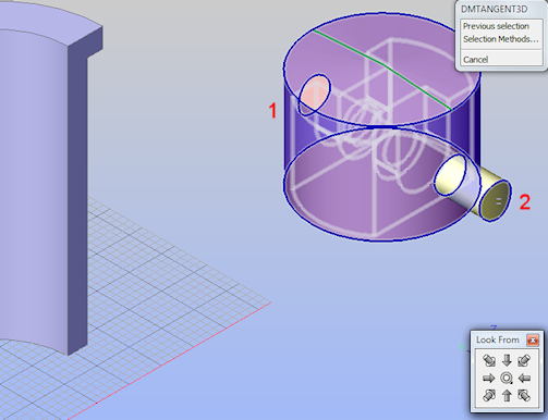
Click the Tangent
tool button (![]() ) on the 3D Constraints toolbar.
) on the 3D Constraints toolbar.
The command bar reads: Select a pair of subentities:
Move the cursor over two cylindrical faces of the
piston (1) and the pin (2) as indicated in the image below.
Hit the TAB key until the correct face highlights, then click and
move the cursor to the second face.
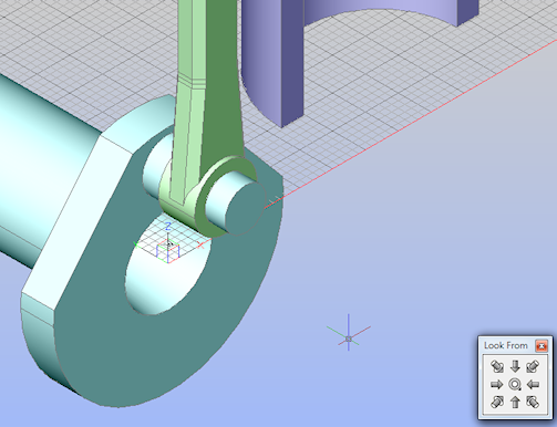
Click the Coincident
tool button (![]() ) on the 3D Constraints toolbar.
) on the 3D Constraints toolbar.
The command bar reads: Select a pair of subentities:
Move the cursor over two planar faces of the
connecting rod (1) and the piston (2) as indicated in the image
below.
Hit the TAB key until the correct face highlights, then click and
move the cursor to the second face.
Click the Concentric
tool button (![]() ) on the 3D Constraints toolbar.
) on the 3D Constraints toolbar.
The command bar reads: Select a pair of subentities:
Move the cursor over two cylindrical faces of the
connecting rod (1) and the pin (2) as indicated in the image
below.
Hit the TAB key until the correct face highlights, then click and
move the cursor to the second face.
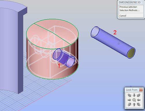
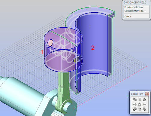
Click the Concentric
tool button (![]() ) on the Constraints toolbar.
) on the Constraints toolbar.
The command bar reads: Select a pair of subentities:
Move the cursor over two cylindrical faces of the
piston (1) and the cylinder (2) as indicated in the image
below.
Hit the TAB key until the correct face highlights, then click and
move the cursor to the second face.
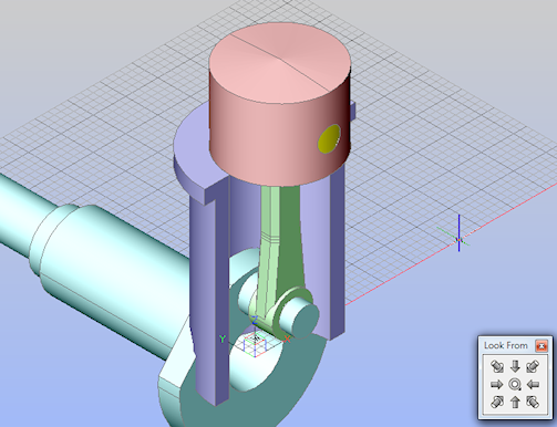
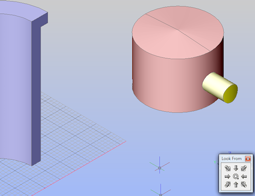
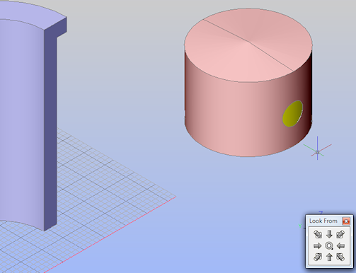
After applying the previous constraint it might be
necessary to correct the position of the cylinder.
Move the cursor over the cylinder, then choose Move (![]() ) in the Quad cursor menu.
) in the Quad cursor menu.
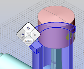
The command bar reads: Enter base point <0,0,0>:
Use an entity snap (e.g. Endpoint) to specify the base point for the move
operation on the cylinder.
The cylinder now moves dynamically with the cursor.
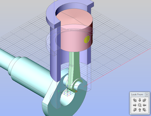
Hold down the Shift key to move the mouse cursor
along the Z-axis.
Click to position the cylinder as shown in the image below.
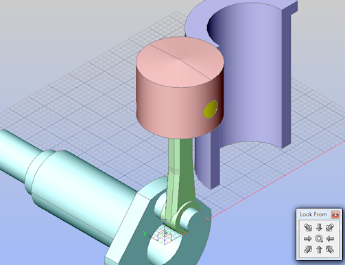
Step 5: Preparing for the kinematic analysis
The piston is correctly positioned inside the cylinder and connected to the crankshaft by the connecting rod.
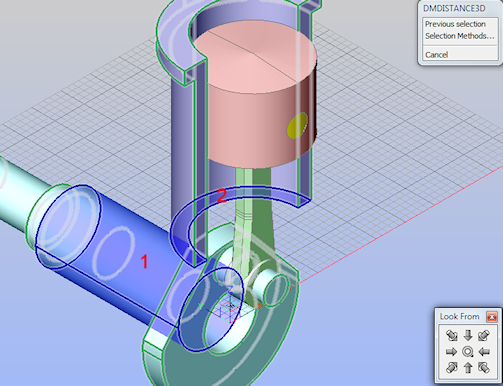
We will now fix the distance between the cylindrical face of the crankshaft and the lower face of the cylinder by applying a dimensional constraint.
Click the Distance
tool button (![]() ) on the 3D Constraints toolbar.
) on the 3D Constraints toolbar.
The command bar reads: Select a pair of subentities:
Select the cylindrical face of the crankshaft (1)
and the lower planar face of the cylinder (2) as indicated in the
image below:
The command bar reads: Enter distance value <133.622>:
A dynamic distance entry field displays.
Type 110 in the dynamic entry field.
The lower face of the cylinder is now fixed at a distance of 110
from the cylindrical face of the crankshaft.
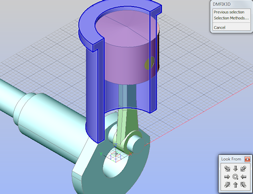
We will fix the cylinder at its current position:
Click the Fix tool
button (![]() ) on the 3D Constraints toolbar.
) on the 3D Constraints toolbar.
The command bar reads: Select an edge, face or 3D solid:
Move the cursor over the cylinder, then hit the TAB key until the body of the cylinder highlights as a whole (see image below).
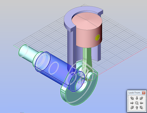
In step 4.1 we have applied a fixation constraint to the body of the crankshaft, which removes all degrees of freedom from the crankshaft. To make it possible to rotate the crankshaft around its axis, it is necessary to remove this constraint and replace it by two fixation constraints: one to the cylindrical face of the crankshaft and one to its planar outer faces.
Click the Fix tool
button (![]() ) on the 3D Constraints toolbar.
) on the 3D Constraints toolbar.
The command bar reads: Select an edge, face or 3D solid:
Move cursor over the cylindrical face of the
crankshaft, then click (see image below)
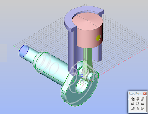
Repeat the previous steps for the planar outer face
of the crankshaft (see image below).
Select the Fix
constraint applied in step 4.1 in the Constraints tree in the Mechanical Browser.
Right click and select Delete in the
context menu.
In this assembly the crankshaft is the driving component. To run the kinematic analysis we will rotate the crankshaft around its axis, which in this case is the Y-axis of the WCS.
Move the cursor over the crankshaft, then choose
Rotate (![]() ) in the Quad cursor menu
) in the Quad cursor menu
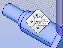
.
The command bar reads: Select axial entity or define axis by
[2Points/Xaxis/Yaxis/Zaxis] <2Points>:
Do one of the following:
Type Y, then press Enter.
Choose Y axis in the prompt menu.
The command bar reads: Pick start point in the rotation plane:
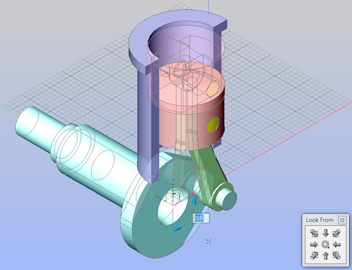
Pick a point in the drawing, then move the mouse to
define the rotation angle.
The piston and the connecting rod move dynamically along with the
rotation of the crankshaft, while the cylinder stays at its fixed
position.
| © Menhirs NV. All rights reserved. |