WCS Top View
UCS Top View
WCS Isometric View
UCS Isometric View
When you create entities in a drawing, they are located in relation to the drawing's underlying Cartesian coordinate system. Every drawing has a fixed coordinate system called the World Coordinate System (WCS).
You can also define arbitrary coordinate systems located anywhere in three-dimensional space. These are called user coordinate systems (UCS) and can be located anywhere in the WCS and oriented in any direction. You can create as many UCS as you want, saving or redefining them to help you construct three-dimensional entities. By defining a UCS within the WCS, you can simplify the creation of most three-dimensional entities into combinations of two-dimensional entities.
When you begin a new drawing, you are automatically in the WCS, indicated by the letter W in the icon. When you display a drawing in plan view, you see the coordinate system icon from the top, with the z-axis directed straight toward you. When you display a three-dimensional drawing in a view other than plan view, the coordinate system icon changes to reflect your new viewpoint.
|
NOTE |
You cannot delete or modify the WCS. |
To help you keep your bearings in the current coordinate system, Bricscad displays a coordinate system icon (UCS icon). The visible portions of the axes are the positive directions.
|
|
|
|
|
|
WCS Top View |
UCS Top View |
WCS Isometric View |
UCS Isometric View |
Three colors represent the three axes, making it easier for you to recognize the orientation in three-dimensional space:
x-axis: red
y-axis: green
z-axis: blue
The Plan View command restores the Plan view or Top view of the current UCS or WCS.
The UCSICON settings variable controls the display and location of the UCS icon:
Show icon:
Controls whether the icon shows or not.
at origin:
Controls the location of the UCS icon: if on, the icon indicates
the origin point of the current coordinate system (UCS or WCS).
However, if the origin is not within the viewport borders,
the UCS icon moves to the corner of the viewport, as defined by the
UCSICONPOS (UCS Icon Position)
settings variable.
When the at origin option is not
checked, the icon always displays in the corner of the viewport
defined by UCSICONPOS.
To define a User Coordinate System
Do one of the following:
Choose Coordinate Systems in the Settings menu.
Type expucs in the command bar, then press Enter.
The Bricscad Explorer - Coordinate Systems dialog opens.
Click the New tool
button (![]() ) on the Bricscad Explorer dialog.
) on the Bricscad Explorer dialog.
The Bricscad Explorer dialog
closes.
The command bar reads:
Current/Entity/Origin/View/X/Y/Z/ZAxis<3point>:
A prompt menu displays:
Press Enter to define the UCS using points.
The command bar reads: New origin <current origin>:
Specify the origin point of the UCS.
The command bar reads: Point of positive X axis <current
point>:
Specify a point to define the positive X-axis.
The command window reads: Point in X-Y plane with positive Y value
<current point>:
Specify a point to define the positive Y-axis.
The UCS is defined.
The Bricscad Explorer dialog
reopens.
Click in the UCS Name field of the newly defined UCS to replace the <NewUCS> default name.
Close the Bricscad Explorer dialog.
|
Keyboard |
Prompt Box |
Description |
|
C |
Current |
Save the current coordinate system. |
|
Enter |
3 point |
Define the coordinate system using points. |
|
E |
Entity |
Align the coordinate system with an entity. |
|
O |
Origin |
Define the origin of the coordinate system. |
|
V |
View |
Align the coordinate system with the current view orientation (1). |
|
X |
X |
Rotate the current coordinate system about its X-axis. |
|
Y |
Y |
Rotate the current coordinate system about its Y-axis. |
|
Z |
Z |
Rotate the current coordinate system about its Z-axis. |
|
ZA |
Z axis |
Define the Z-axis of the new coordinate system (2). |
|
Esc |
Cancel |
Abort the command. |
(1) X-axis is parallel to the bottom edge of the screen and Z-axis perpendicular to the view orientation, positive Z-axis pointing to the viewer. The origin is copied from the previous coordinate system.
(2) The first point defines the origin of the UCS. The second point defines the positive Z-axis. The XY-plane is perpendicular to the Z-axis with the X-axis horizontal and the Y-axis pointing upwards.
Type UCS in the
command bar, then press Enter.
The command bar reads:
?/3point/Delete/Entity/Origin/Previous/Restore/Save/View/X/Y/Z/Zaxis/<World>:
A prompt menu displays.
Do one of the following:
Press Enter to accept the default option.
Choose World in the prompt menu.
Type W in the command bar and press Enter.
Do one of the following:
Choose Coordinate Systems in the Settings menu.
Type expucs in the command bar, then press Enter.
The Bricscad Explorer - Coordinate Systems dialog opens.
Click the blank tile in front of the UCS name to
make it current.
Close the Bricscad Explorer dialog.
|
NOTE |
If no UCS is marked, the WCS is the current coordinate system. |
Do one of the following:
Click the UCS... tool button (![]() ) on the Settings toolbar.
) on the Settings toolbar.
Choose UCS... in the Settings menu.
Type setucs in the command bar, then press Enter.
The User Coordinate System dialog opens.
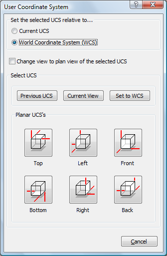
Choose one of the following:
Set the selected UCS relative to the Current UCS.
Set the selected UCS relative to the World coordinate system (WCS).
(option) Enable the Change view to plan view of the selected UCS option.
Click one of the Planar
UCS's buttons.
The User Coordinate System dialog closes.
| Bricscad™ is commercialized by Bricsys NV. Bricsys NV and Vondle NV are fully owned subsidiaries of Menhirs NV. © 2001- Menhirs NV - All rights reserved. |