Do on of the following:
Click the Real-Time
Sphere tool button (![]() ) on the View toolbar.
) on the View toolbar.
Choose Real-Time Motion > Real-Time Sphere in the View menu.
Type rtrot in the command bar, then press Enter.
In order to view your drawing from any angle, you can rotate a view. The Real-Time Motion tools of Bricscad allow you to rotate a view in real-time. You can rotate the view about the X, Y or Z screen axis or in any direction (real-time sphere). If the Continuous Motion variable is set, the view rotation continues until you conclude the Real-Time Motion command.
|
NOTES |
|
Do on of the following:
Click the Real-Time
Sphere tool button (![]() ) on the View toolbar.
) on the View toolbar.
Choose Real-Time Motion > Real-Time Sphere in the View menu.
Type rtrot in the command bar, then press Enter.
The command bar reads: >> ENTER, Right click or Esc to complete ...
Press and hold the left mouse button.
Move the mouse to rotate the view in any direction.
To abort the Real-Time Sphere command, do one of the following:
Right click.
On the keyboard, press Enter, space bar or Esc.
Rotating a view about the view X-axis
Do on of the following:
Click the Real-Time
X tool button (![]() ) on the View toolbar.
) on the View toolbar.
Choose Real-Time Motion > Real-Time X in the View menu.
Type rtrotx in the command bar, then press Enter.
The command bar reads: >> ENTER, Right click or Esc to complete ...
Press and hold the left mouse button.
Move the mouse to rotate the view.
To abort the Real-Time X command, do one of the following:
Right click.
On the keyboard, press Enter, space bar or Esc.
Rotating a view about the view Y-axis
Do on of the following:
Click the Real-Time
Y tool button (![]() ) on the View toolbar.
) on the View toolbar.
Choose Real-Time Motion > Real-Time Y in the View menu.
Type rtroty in the command bar, then press Enter.
The command bar reads: >> ENTER, Right click or Esc to complete ...
Press and hold the left mouse button.
Move the mouse to rotate the view.
To abort the Real-Time Y command, do one of the following:
Right click.
On the keyboard, press Enter, space bar or Esc.
Rotating a view about the view Z-axis
Do on of the following:
Click the Real-Time
Z tool button (![]() ) on the View toolbar.
) on the View toolbar.
Choose Real-Time Motion > Real-Time Z in the View menu.
Type rtrotz in the command bar, then press Enter.
The command bar reads: >> ENTER, Right click or Esc to complete ...
Press and hold the left mouse button.
Move the mouse to rotate the view.
To abort the Real-Time Z command, do one of the following:
Right click.
On the keyboard, press Enter, space bar or Esc.
Do one of the following:
Click the Set
Viewpoint ... tool button (![]() ) on the View toolbar.
) on the View toolbar.
Choose Set Viewpoint ... in the View menu.
Type ddvpoint in the command bar, then press Enter.
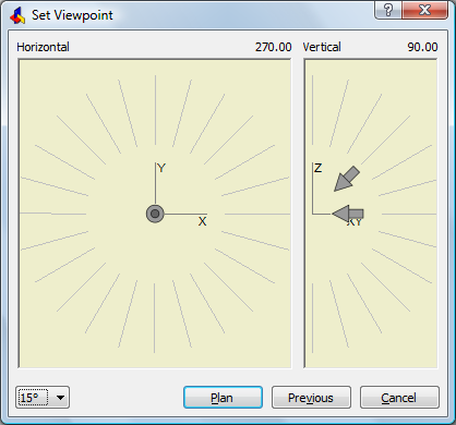
The Preset Viewpoint dialog opens.
Click the Angle
Precision button (![]() ) to choose a different display
mode for the Set Viewpoint
dialog.
) to choose a different display
mode for the Set Viewpoint
dialog.
Then choose either 45°, 15° or 5°.
|
|
|
45° display mode |
In 15° or
5° mode
click in the inner area of the Horizontal and Vertical fields to choose a 45° display mode viewpoint.
Click in the outer area of the Horizontal and Vertical fields to choose another angle.
To set the Vertical view angle, do one of the following:
Skip this step to accept the default vertical view directions:
Horizontal for East, North, West and South.
Downwards for the other directions.
If both the down- and left-arrow show in the Vertical field, the default vertical view directions are active.
Select a 45°
mode angle in the inner area, then click to confirm your
choice.
A single arrow indicates the selected vertical view direction.
If in 15° or
5° mode
in, select a view direction in the outer area, then click to
confirm your choice.
The selected angle displays in bold.
The view is updated as you click.
To set the Horizontal view angle, do one of the following:
Select a 45°
mode angle in the inner area, then click to confirm your
choice.
An arrow indicates the selected horizontal view direction.
The perspective of the arrow reflects the vertical view
direction.
If in 15° or
5° mode
in, select a view direction in the outer area, then click to
confirm your choice.
The selected angle displays in bold.
The view is updated as you click.
|
NOTE |
Use the Isometric Views toolbar for standard view rotations: top, front, back, left, right and isometric views. |
Do one of the following:
Click the Plan
View tool button (![]() ) on the View toolbar.
) on the View toolbar.
Choose Plan View in the View menu.
Type plan in the command bar, then press Enter.
The command bar reads: Plan view of: UCS/World/<current UCS>:
A prompt menu opens:
Press Enter to restore the plan view with respect to the current coordinate system.
|
Keyboard |
Prompt Box |
Description |
|
Enter |
Current |
(default command option) Restore the plan view with respect to the current coordinate system. |
|
U |
UCS |
Show the plan view of a saved User Coordinate System. You are prompted to type the name of a UCS. |
|
W |
World |
Show the plan view with respect to the World Coordinate System (WCS). |
|
NOTES |
|
| Bricscad™ is commercialized by Bricsys NV. Bricsys NV and Vondle NV are fully owned subsidiaries of Menhirs NV. © 2001- Menhirs NV - All rights reserved. |