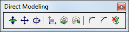
This section describes direct modeling operations offered by BricsCAD. These operations are available from the Quad tool.
Alternatively you can use Direct Modeling Menu or Direct Modeling Toolbar:
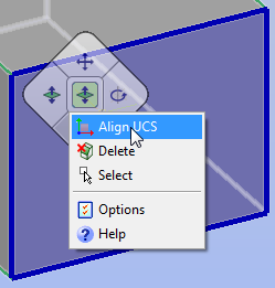
The Align UCS tool (![]() ) launches the UCS command with the
Face option selected.
) launches the UCS command with the
Face option selected.
The following direct modeling operations are available in BricsCAD:
|
Icon |
Command |
Applies to |
Description |
|
|
Planar, cylindrical, spherical, conical and toroidal faces of a solid. Closed 2D entities, attached to a solid. |
Faces: adds volume to, or removes volume from the solid by cursor movement or direct distance input. Closed 2D entity (If attached to a face of a solid): creates a solid by extruding the 2D entity. The height of the extrusion is specified by cursor movement or direct distance input. Depending on the extrusion direction the newly created solid is unified with or subtracted from the existing solid the 2D entity was attached to. |
|
|
|
Cylindrical, spherical, conical and toroidal faces of a solid. Linear and circular edges of a solid. Solids. |
Moves the selected geometry using a vector in the XY- plane of the current UCS. When a face or an edge of a solid is moved, adjacent faces and edges are adjusted to preserve the correct solid topology.
|
|
|
|
Planar, cylindrical, spherical, conical and toroidal faces of a solid. Solids. |
Rotates the selected geometry around an axis. When a face of a solid is rotated, adjacent faces and edges are adjusted to preserve the correct solid topology. |
|
|
|
Sharp edges of a solid. |
Creates a fillet between adjacent faces sharing a sharp edge(s). |
|
|
|
Sharp edges of a solid. |
Creates a chamfer between adjacent faces sharing a sharp edge(s). |
|
|
|
Closed 2D entities. |
Creates solids by extruding the selected 2D entities. |
|
|
|
Closed 2D entities. |
Creates a solid by revolving a 2D entity about an axis. |
|
|
|
Faces of a solid. Closed 2D entities. Solids. |
Deletes the selected entities.When faces of a solid object are deleted, the gap is filled by extending the adjacent faces. |
Press and hold the TAB key to select obscured geometry.
If a direct modeling command is entered at the command prompt or selected in a menu or toolbar, you need to press the Enter key (or right click) to conclude the selection procedure.
If launched from the Quad cursor menu, the command is executed when you click to confirm the selection of the currently highlighted geometry; press and hold the Ctrl key to select multiple entities.
When using the dmPushPull command a dynamic dimension displays. Type the desired distance or radius in the dynamic field, then press Enter to confirm.
The initial distance is measured from the previous position of the face. Repeatedly press the TAB key to cycle through the distances to other references planes (if any). Reference planes are parallel to the face being pushpulled. Press and hold the Shift key, then press the TAB key to cycle in reverse order.
Typically holes are made using the SUBTRACT command.
When pushpulling a closed 2D entity that lies on a face of a solid, a hole is created when you push the 2D entity inside the solid.
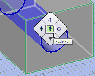
Hover over the face of the solid, then click the
bottom quadrant of the Quad cursor menu
and choose Align UCS from the context
menu.
Right click to accept the UCS.
Draw a circle on the face of the solid.
Hover over the circle, then choose Push/Pull in the Quad cursor menu.
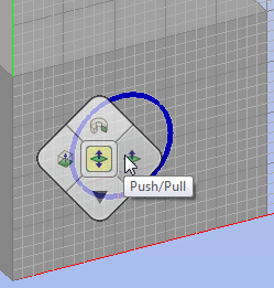
Push the circle inside the solid.
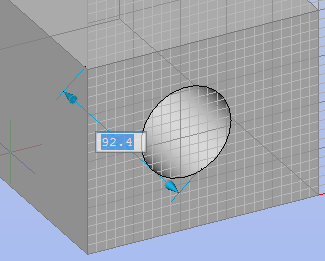
Do one of the following:
Type a distance in the dynamic field to define the depth of the hole.
Push the circle through the solid.
(option) Choose Push/Pull in the Quad cursor menu. to modify the diameter of the hole.
(option) Use the dmDistance3d command to apply distance constraints between the side faces of the solids and the cylindrical surface of the hole to control the position of the hole.
(option) Use the dmRadius3d command to control the diameter of the hole through a dimensional constraint.
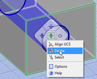
To delete a hole, you must delete all internal faces and/or surfaces of the hole.
Hover over the cylindrical surface of the hole.
Click the bottom quadrant of the Quad cursor menu and choose Delete from the context menu.
Hover over one of the visible internal faces of the
hole.
The face highlights.
Press and hold the Ctrl key, then click to select
the face.
The face remains highlighted.
Press and hold the Ctrl key, then hover over the
other visible internal face of the hole and click to select when
the face highlights.
Both selected faces remain highlighted.
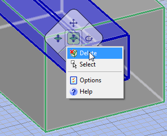
Release the Ctrl key, then hover over one of the obscured internal faces of the hole and repeatedly press the TAB key until the face highlights.
Press and hold the Ctrl key and click to select the face.
Repeat steps 4 and 5 to select the other obscured face.
With all the faces highlighted, click the bottom quadrant of the Quad cursor menu and choose Delete from the context menu.
| © Menhirs NV. All rights reserved. |