Inserting Blocks
Commands: INSERT,
-INSERT,
INSERTALIGNED
and MINSERT
The Insert command lets you insert
blocks through a dialog box.
The -Insert command inserts blocks
by prompting in the command bar. BricsCAD will lookup the block
name in the block definitions in the current drawing. If the block
is not found in the current drawing, the paths defined by the
SRCHPATH system variable are
searched. If the block is not found there either, BricsCAD responds
'Could not find file <blockname>'
The Insertaligned command inserts
a block entity, with easy alignment on existing entities. The
Insertaligned command is similar to
the Insert command, but during the
placement the block will be dynamically aligned with existing
lines, polylines, arcs or circles. The block is aligned with the
entity to which the cursor snaps. If no entity is snapped, the
block is aligned with the X-axis of the WCS.
The Minsert command Inserts a
block as a rectangular array; combines the -Insert and Array
commands (short for "multiple insertion").
You can choose to select an existing block definition or to
insert an entire drawing as a block. When you insert a drawing, a
new block definition is created in the current drawing. If you
change the original drawing file, those changes have no effect on
the current drawing unless you redefine the block by reinserting
the changed drawing. When a block is inserted in a drawing, it is
treated as a single entity.
General procedure to insert a
block:
-
Specify a block definition or drawing file.
-
Specify the insertion point.
-
Specify the scale.
-
Specify the rotation angle.
|
NOTES
|
-
When inserting a drawing as a block, the base
point, as defined by the INSBASE
system variable, of the inserted drawing is the origin point of the
block. The INSBASE system variable is
set by the BASE command.
-
If a block contains attributes
you will be prompted to fill out the text for each attribute in the
command bar.
-
If the DRAGOPEN
system variable is set to zero (OFF), drawings can be inserted as a
block by dragging them from the Windows
Explorer dialog into the current drawing; if DRAGOPEN = 1 (ON), the drawing will be opened
instead.
-
The INSUNITS
system variable defines a drawing units value for automatic scaling
when inserting blocks or attaching
Xrefs (see scheme below).
|
|
|
INSUNITS in the target drawing
|
|
INSUNITS
in the source drawing
|
Centimeters
|
Inches
|
not specified
(INSUNITSDEFTARGET
= Centimeters)
|
|
Millimeters
|
|
|
|
|
Inches
|
|
|

|
|
not specified
(INSUNITSDEFSOURCE
= Inches)
|
|
|
|
|
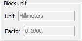
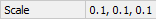
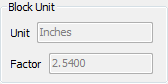
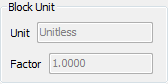
The Unit field under Block Unit is set by the INSUNITS (Insertion Units) settings variable in
the source drawing. The Factor field
expresses the relation between the value of the INSUNITS variable in the source drawing and the
target drawing. E.g. if INSUNITS is
Millimeters in the source drawing and Centimeters in the target
drawing, the value of the Factor
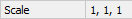
field is 0.1. The Scale factor of the
block is 1,1,1.
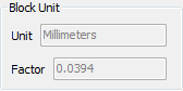
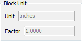
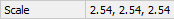
If INSUNITS in the source drawing
is Unspecified (unitless), INSUNITSDEFSOURCE is used. The value of the
Factor field is 1.0 and the
Scale factor of the block expresses
the relation between INSUNITSDEFSOURCE and INSUNITS in the target drawing.
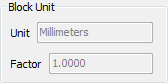
If INSUNITS in the target drawing
is Unspecified (unitless), INSUNITSDEFTARGET is used. The value of the
Factor field is 1.0 and the
Scale factor of the block expresses
the relation between INSUNITS in the
source drawing and INSUNITSDEFTARGET.
If INSUNITS is unspecified
(unitless) in both the source and the target drawing, INSUNITSDEFSOURCE and INSUNITSDEFTARGET are used. The value of the
Factor field is 1.0 and the
Scale factor of the block expresses
the relation between INSUNITSDEFSOURCE and INSUNITSDEFTARGET.
The values of INSUNITSDEFSOURCE and INSUNITSDEFTARGET are saved in the registry and
therefore apply to all drawings in which INSUNITS is unspecified (unitless).
|
To insert a block
-
Do one of the following
-
Click the Insert
Block... tool button () on the Insert toolbar.
-
Choose Insert
Block... in the Insert
menu.
-
Type insert in
the command bar, then press Enter.
The Inserts dialog
opens.
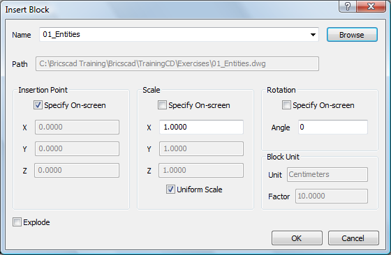
-
In the Inserts
dialog, do one of the following:
-
Select an existing block definition in the
Name list.
-
Click the Browse button and select a drawing file.
-
(option) Check the
Explode option to explode the block after insertion.
-
(option) Uncheck the Specify
On-Screen option, then specify the Insertion Point by keying in the coordinates in
the X, Y and Z fields.
-
(option) Uncheck the Specify
On-Screen option, then specify the Scale by keying in the scaling factors in the
X, Y
and Z fields.
Check the Uniform Scale option to
equal the X, Y and Z scale
factors.
-
(option) Check the Specify
On-Screen option to specify the Rotation angle when
inserting the block.
-
Click the OK
button.
The command bar reads: Insertion point for block.
A prompt menu displays.
-
Specify the insertion point.
The command bar reads: Corner/XYZ/X scale factor
<1.000000>:
A prompt menu displays.

-
Right click or press Enter to accept the default
X scale factor.
The command bar reads: Y scale factor: <Equal to X scale
(1.000000)>:
-
Right click or press Enter to set the Y scale factor equal to the X scale factor.
The block is inserted.
To insert a block
using the Drawing Explorer
Inserting internal blocks
-
Open the Drawing
Explorer - Blocks dialog.
-
(optional) Choose either Detail View ( ) or Icon
View (
) or Icon
View ( ).
).
-
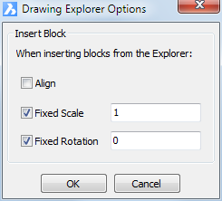
(option) Edit the insert options:
-
Choose Options... in the Settings menu or select a block, then right click
and choose Options ... in the context
menu.
-
Set the insert options in the Drawing Explorer Options dialog box.
-
Do one of the following:
Select a block, then do one of the following:
-
Click the Insert
Block button ( ) on the Details toolbar.
-
Right click and select Insert from the context menu
-
When in Icon
View, double click the block.
To select an external drawing, do one of the
following:
-
Click the Insert
External tool button ( ) on the Details toolbar.
-
Choose Insert
External in the Edit menu.
-
Right click, then choose Insert External in the context menu.
The Drawing Explorer -
Blocks window closes.
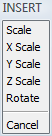
The command bar reads: Multiple
blocks/Scale/<Insertion point for block>:
A prompt menu displays
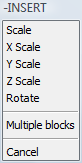
-
Follow the instructions in the command bar to
insert the block.
The Drawing Explorer - Blocks window
reopens.
-
(option) Insert more blocks.
-
Close the Drawing Explorer -
Blocks window.
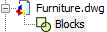
Inserting blocks from another
drawing
 Block
Manager (Internet connection needed)
Block
Manager (Internet connection needed)
-
Open the Drawings Explorer.
-
In the Drawings pane,
click the Folders tab.
-
(option) If necessary,
add the folder of the drawing.
-
Click the Expand icon
(+) in front of the drawing.
The Blocks icon of the drawing
displays.
-
Click the Blocks
icon.
The blocks in the drawing display in the Details pane.
If necessary, click the Icon View
button () in the Details toolbar to see thumbnail images of the
blocks.
-
(option) Edit the insert options:
-
Choose Options... in the Settings menu or select a block, then right click
and choose Options ... in the context
menu.
-
Set the insert options in the Drawing Explorer Options dialog box.
The available options are:
-
Align: If
checked, launches the InsertAligned command to
insert the block.
When the Align option is checked, the
Fixed Scale and Fixed Rotation options are not available.
-
Fixed Scale: If
checked, allows to insert the block at a fixed scale.
-
Fixed Rotation:
If checked, allows to insert the block at a fixed rotation.
-
To insert a block, do one of the following:
-
Click the Insert
Block button () on the Details toolbar.
-
When in
Icon View, double click the thumbnail image of the block.
-
When in
Detail view, double click the number in front of the block
name.
The Drawing Explorer
dialog closes temporarily to let you insert the block in the
drawing.
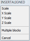
The command bar reads: Multiple
blocks/<Insertion point for block>:
A prompt menu displays
-
Follow the instructions in the command bar to
insert the block.
The Drawing Explorer window
reopens.
-
(option) Insert more blocks.
-
Close the Drawing Explorer -
Blocks window.
To insert a block
aligned with an entity
-
Make sure the appropriate
Entity Snaps are active.
-
Type insertaligned or
insal in the command bar, then press
Enter.
The command bar reads: ? to list blocks in drawing/~ to open the
file dialog/<Block to insert> <name>:
-
Do one of the following:
-
Press Enter or right click to insert the most
recently placed block again.
-
Type the name of an existing block definition
in the command bar, then press Enter.
-
Type the name of an external block file in
the command bar, then press Enter.
-
Type ~ (tilde)
then press Enter to open the file dialog.
The command bar reads: Multiple
blocks/<Insertion point for block>:
A prompt menu displays.
-
Snap to an entity.
The block is aligned with the entity.
-
Click to define the insertion point.
When you move the crosshairs, the block is mirrored about the
selected entity or a about a line tangent to the selected
entity.
-
Click to specify the mirroring of the block.
|
NOTE
|
If you type the name of block in step 3, BricsCAD will lookup
the block in the block definitions in the current drawing. If the
block is not found in the current drawing, the paths defined by the
SRCHPATH system variable are
searched. If the block is not found there either, BricsCAD responds
'Could not find file <blockname>'
|
|
NOTE
|
The block is aligned as follows: The block is rotated so that
its local Z-axis is parallel with the Z-axis of the active UCS, and
its local X-axis should be parallel with the tangent to the entity
at the position of the snap point. When you click a point on an
entity the block is aligned with the entity. Then, by moving the
mouse pointer around the insertion point, you can choose how the
block should be mirrored. The origin point of the block lies on the
entity.
|
To insert multiple instances of a block in a rectangular
array
-
Type minsert in the
command bar, then press Enter.
The command bar reads:
? to list blocks in drawing/~ to open the file dialog/<Block to
insert>:
-
Do one of the following:
-
Type ~
(press and hold the Alt gr key,
then press the ~ key), then press
Enter.
The Insert Block file dialog
displays.
Select the drawing file you want to insert and press the
Open button (or double click the file
name).
-
Press Enter to accept the <Block to
insert>.
-
Type a block name, then press Enter.
Optionally, type ? to display search for existing block
definitions.
-
The block is attached to the cursor.
The command bar reads: Multiple blocks/<Insertion point for
block>:
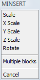
-
Specify the insertion point.
The command bar reads: Corner/XYZ/X scale factor <1.00>:
-
To define the X scale factor, do one of the
following:
-
Press Enter to accept the default .
-
Type the X scale factor, then press
Enter.
-
Click to define the X scale factor
graphically.
The command bar reads: Y scale factor: <Equal to
X scale (current X scale)>:
-
Repeat step 5 to define the Y scale factor.
The command bar reads: Rotation angle for block <0>:
-
Do one of the following:
-
Press Enter to set the rotation angle to
0°.
-
Type a rotation angle, then press Enter.
Click to define the rotation angle graphically.
The command bar reads: Number of rows in the array <1>:
-
Type the number of rows, then press Enter or press
Enter for one row.
The command bar reads: Number of columns <1>:
-
Type the number of columns, then press Enter or
press Enter for one column.
The command bar reads: Vertical distance between rows, or spacing
rectangle:
-
Type the row spacing distance, then press
Enter.
The command bar reads: Horizontal distance between columns:
-
Type the column spacing distance, then press
Enter.
The block array is created as a single entity.
|
NOTES
|
-
If you choose Multiple
blocks in step 3, you are prompted to create multiple
instances of the block array.
-
If a block array is
exploded, all blocks in the array are exploded.
-
If you type the name of block in step 2,
BricsCAD will lookup the block in the block definitions in the
current drawing. If the block is not found in the current drawing,
the paths defined by the SRCHPATH
system variable are searched. If the block is not found there
either, BricsCAD responds 'Could not find file
<blockname>'
|
|
© Menhirs NV. All rights reserved. |