View Rotation
Commands: RTROT, RTROTCTR, RTROTF, RTROTX, RTROTY, RTROTZ, DDVPOINT, -VIEW, PLAN and VPOINT
The Rtrot (Real-Time Constrained
Sphere) command rotates 3D drawings in real-time.
The Rtrotctr (Real-time Sphere
Center) command freely rotates 3D drawings in real-time about a
user-defined center point.
The Rtrotf (Real-time Free Sphere)
command freely rotates 3D drawings in real-time.
The Rtrotx , Rtroty and Rtrotz
commands rotates 3D drawings in real-time about the x, y or z
screen axis.
The Ddvpoint command sets 3D
viewpoints or plan view, through a dialog box (short for "dynamic
dialog view point").
The Plan command displays the plan
viewpoint of drawings.
The Vpoint command changes the 3D
viewpoint.
In order to view your 3D drawings from any angle, you can rotate
a view. The Real-Time Motion tools of
BricsCAD allow you to rotate a view in real-time. You can rotate
the view about the X, Y or Z screen axis or in any direction
(real-time sphere). If the Continuous
Motion variable is set, the view rotation continues until
you conclude the Real-Time Motion
command.
See also: View manipulation
using the mouse.
|
NOTE
|
'Real-time' commands should not be used when drawing in 2D. Use
the Plan View tool
to restore top view.
|
The Look From
control
The Look From control allows to
select a number of preset views such as orthographic views and
isometric views. By default the Look
From control displays in the top right corner of the graphic
screen.
If the UCSORTHO
system variable is ON an orthographic
UCS is restored automatically when the related orthographic view is
chosen on the Look From control.
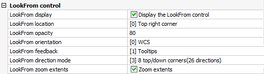
System Variables
The behavior of the Look From
control depends on a number of system variables and user
preferences
|
Name
|
Title
|
Description / Options
|
|
NAVVIEWCUBEDISPLAY
|
Look From Display
|
Controls whether the Look From
control displays.
|
|
NAVVIEWCUBELOCATION
|
Look From Location
|
Controls the location of the Look
From control in the graphic screen.
The options are:
0: Top right corner.
1: Top left corner
2: Bottom left corner
3: Bottom right corner
|
|
NAVVIEWCUBEOPACITY
|
Look From Opacity
|
Sets the opacity of the Look From
control when not active.
Values between 1 (invisible) and 100 (no dimming) are
accepted.
|
|
NAVVIEWCUBEORIENT
|
Look From Orientation
|
Specifies the view orientation reference: either the WCS (World
Coordinate System or the current UCS (User Coordinate System).
|
|
LookFromFeedback
|
Look From Feedback
|
Controls the display and location of tooltips.
0: No tooltips
1: Tooltips next to the Look From
control.
2: Tooltips in the status bar.
|
|
LookFromDirectionMode
|
Look From Direction Mode
|
Specifies the number of available view directions.
Holding down the Ctrl-key switches between top-down and
bottom-up view directions
0: Orthogonal views only (6 directions).
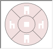
1: 6 Orthogonal views and 8 Isometric views (14 directions).
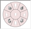
2: 4 Rotated orthogonal, 6 Orthogonal and 8 Isometric views (18
directions)
3: 8 Rotated isometric, 4 Rotated orthogonal, 6 Orthogonal and 8
Isometric views (26 directions).
|
|
LookFromZoomExtents
|
Look From Zoom Extents
|
Determines whether a 'zoom extents' is performed whenever a
new view direction is selected.
|
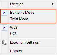
Setting the Look From mode
- Move the cursor to the Look
From control.
- Right click, then select either Isometric Mode or Twist
Mode in the context menu.
Using the Look From control in Isometric mode
Isometric mode is best used in 3D models.
- Move the cursor to the Look
From control.
The Look From control becomes
active.
- Position the cursor on the Look From control to choose a view
orientation.
A preview image and a tooltip indicate the currently selected view
orientation.
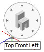
- Click to confirm.
The view is updated.
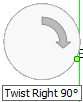
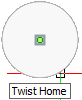
Using the Look From control in Twist mode
Twist mode is best used in 2D drawings.
In Twist mode, the Loofk From control allows to rotate the view
around the screen Z-axis
- Move the cursor to the Look
From control.
The Look From control becomes
active.
- Do one of the following:
- Move the cursor on the edge of the the
Look From control. Left half for
counterclockwise, right half for clockwise rotation. Click when the
arrow is at the desired rotation angle.
The following angles are available: 15°, 30°,45°, 60°, 90°, 120°,
135° and 180°, both clockwise and counterclockwise.
If LookFromFeedback = 1, the angle
displays in a tooltip.
Click again to rotate over the same angle again.
- Move the cursor to the center of the
Look From control, then click to
restore the view (= unrotated state).
Rotating a view
freely
- Do one of the following:
- Click the Real-Time
Constrained Sphere tool button (
 )
)
or the Real-Time Sphere tool button
( ) on the Real-Time Motion toolbar.
- Choose Real-Time
Motion > Real-Time Constrained
Sphere
or Real-Time Motion > Real-Time Sphere in the View menu.
- Type rtrot ,
rtrotf or rtrotctr in the command bar, then press
Enter.
The command bar reads: >> Press ENTER or Esc
to complete, or right click to display context menu ...
- Press and hold the left mouse button.
Move the mouse to rotate the view.
- Using the Real-Time
Constrained Sphere command horizontal mouse movement
(parallel to the screen X-axis) rotates the 3D model about the
world Z-axis.
- Using the Real-time
Sphere Center command you are prompted to specify a center
point for the rotation first.
- (option) Right click to display a context
menu:
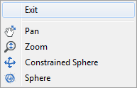
- To abort the Real-Time
Sphere commands, do one of the following:
- Right click, then choose Exit in the context menu..
- Press Enter, space bar or Esc.
Rotating a view
about the view X-axis
- Do one of the following:
- Click the Real-Time
X tool button (
 ) on the Real-Time Motion toolbar.
- Choose Real-Time
Motion > Real-Time X in the
View menu.
- Type rtrotx in
the command bar, then press Enter.
The command bar reads: >> Press ENTER or Esc
to complete, or right click to display context menu ...
- Press and hold the left mouse button.
Move the mouse to rotate the view.
- (option) Right click to display a context
menu:
- To abort the Real-Time
X command, do one of the following:
- Right click.
- Press Enter, space bar or Esc.
Rotating a view
about the view Y-axis
- Do one of the following:
- Click the Real-Time
Y tool button (
 ) on the Real-Time Motion toolbar.
- Choose Real-Time
Motion > Real-Time Y in the
View menu.
- Type rtroty in
the command bar, then press Enter.
The command bar reads: >> Press ENTER or Esc
to complete, or right click to display context menu ...
- Press and hold the left mouse button.
Move the mouse to rotate the view.
- (option) Right click to display a context
menu:
- To abort the Real-Time
Y command, do one of the following:
- Right click.
- Press Enter, space bar or Esc.
Rotating a view
about the view Z-axis
- Do one of the following:
- Click the Real-Time
Z tool button (
 ) on the Real-Time Motion toolbar.
- Choose Real-Time
Motion > Real-Time Z in the
View menu.
- Type rtrotz in
the command bar, then press Enter.
The command bar reads: >> Press ENTER or Esc
to complete, or right click to display context menu ...
- Press and hold the left mouse button.
Move the mouse to rotate the view.
- (option) Right click to display a context
menu:
- To abort the Real-Time
Z command, do one of the following:
- Right click.
- Press Enter, space bar or Esc.
Using Preset
Viewpoints
- Do one of the following:
- Click the Set
Viewpoint ... tool button (
 ) on the View toolbar.
- Choose Set Viewpoint
... in the View menu.
- Type ddvpoint
in the command bar, then press Enter.
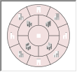
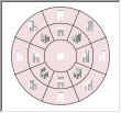
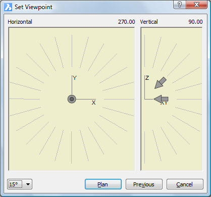
The Preset Viewpoint
dialog opens.
- Click the Angle
Precision button (
 ) to choose a different display
mode for the Set Viewpoint
dialog.
) to choose a different display
mode for the Set Viewpoint
dialog.
Then choose either 45°, 15° or
5°.
|
|
|
45° display mode
|
In 15° or
5° mode
click in the inner area of the Horizontal and Vertical fields to choose a 45° display mode viewpoint.
Click in the outer area of the Horizontal and Vertical fields to choose another angle.
- To set the Vertical
view angle, do one of the following:
- Skip this step to accept the default
vertical view directions:
-
Horizontal for East, North, West and South.
-
Downwards for the other directions.
If both the down- and left-arrow show in the
Vertical field, the default vertical
view directions are active.
- Select a 45°
mode angle in the inner area, then click to confirm your
choice.
A single arrow indicates the selected vertical view direction.
- If in 15° or
5° mode
in, select a view direction in the outer area, then click to
confirm your choice.
The selected angle displays in bold.
The view is updated as you click.
- To set the Horizontal view angle, do one of the
following:
- Select a 45°
mode angle in the inner area, then click to confirm your
choice.
An arrow indicates the selected horizontal view direction.
The perspective of the arrow reflects the vertical view
direction.
- If in 15° or
5° mode
in, select a view direction in the outer area, then click to
confirm your choice.
The selected angle displays in bold.
The view is updated as you click.
|
NOTE
|
Use the Isometric
Views toolbar for standard view rotations: top, front, back,
left, right and isometric views.
|
Restoring Plan
View
- Do one of the following:
- Click the Plan
View tool button (
 ) on the View toolbar.
- Choose Plan
View in the View menu.
- Type plan in
the command bar, then press Enter.
The command bar reads: Plan view of:
UCS/World/<current UCS>:
A prompt menu opens:
- Press Enter to restore the plan view with respect
to the current coordinate system.
|
NOTES
|
-
If the WCS is the current coordinate system, the
Current and World options have the same result.
-
If the UCSFOLLOW
variable is set to ON, the plan view
is generated whenever the UCS changes.
|
|
© Menhirs NV. All rights reserved. |