![]() Pro, Platinum
Pro, Platinum![]() Pro, Platinum
Pro, Platinum![]() Pro, Platinum
Pro, Platinum
Creates materials and edits their properties through the Drawing Explorer.
Accessing the Command
command bar: materials
menu bar: Tools | Drawing Explorer | Materials ...
toolbar: Rendering| ![]()
: materials
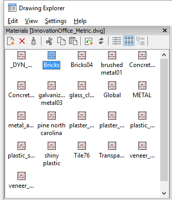
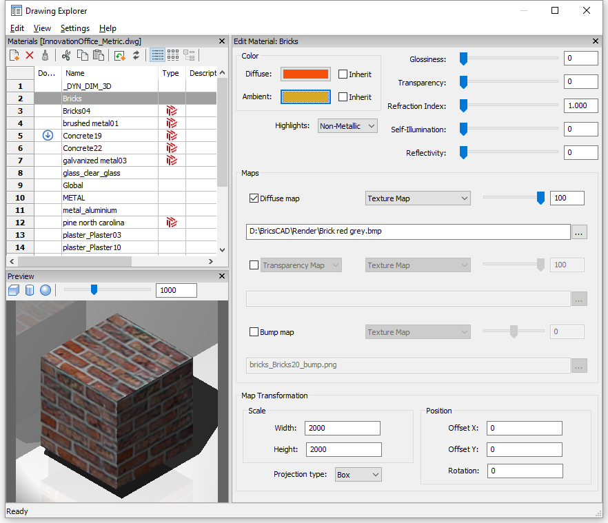
Displays the Materials section of the Drawing Explorer dialog box:
RedWay materials (![]() ), which are imported in the
Materials Browser, cannot be
edited. All settings for such materials are greyed out, except for
the Map Transformation settings.
), which are imported in the
Materials Browser, cannot be
edited. All settings for such materials are greyed out, except for
the Map Transformation settings.
Right click a Redway material, then choose Convert to regular material in the context menu to activate all settings fields.
Command Options
|
Option |
Description |
|
Details |
|
|
Creates a new material. Click the icon, then name the material and optionally fill out the description field (Detail View only). |
|
|
Deletes the selected material(s). The Global material cannot be deleted. |
|
|
Displays the Icon View of the materials:
Select a material to edit its properties. Click the material name to rename. |
|
|
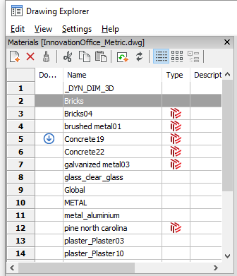
Displays the Detail View of the materials:
Select a material to edit its properties. Click the Material Name field to rename. Click the Description field to add or edit the material description. Double click the Download icon ( |
|
|
|
|
|
|
|
|
Displays a preview of the selected material applied to a cube. |
|
|
Displays a preview of the selected material applied to a cylinder. |
|
|
Displays a preview of the selected material applied to a sphere. |
|
|
Sets the light intensity in the Preview window. Do one of the following:
|
|
|
|
|
|
Edit Material |
|
|
Name |
Type a name for the material. The material name must be unique. The Global material cannot be renamed. |
|
Description |
Type a description for the material. The material description is optional. |
|
|
|
|
|
|
|
Diffuse Ambient
|
Sets the diffuse and ambient color. Do one of the following:
|
|
Highlights |
Sets the highlight property of the material. Click the button then choose either Non-Metallic or Metallic. |
|
Glossiness Transparency Refraction Index Self-Illumination Reflectivity |
Defines a property of the material surface. Do one of the following:
|
|
|
|
|
Texture maps add detail to a surface which is not included in the 3D model itself. To apply a texture map:
(*) The TextureMapPath user preference defines the search path for texture map images. In the BricsCAD program folder exist three subfolders under Textures, each containing a number of texture files of the same name. Images in folder 1 have a size of 256 x 256 pixels, folder 2 contains images of 512 x 512 pixels, images in folder 3 have a size of 1024 x 1024 pixels. If the Diffuse map setting of a material uses the image name only (not path), you can control the quality of a rendered image by setting the TextureMapPath user preference to folder 1, 2 or 3. |
|
|
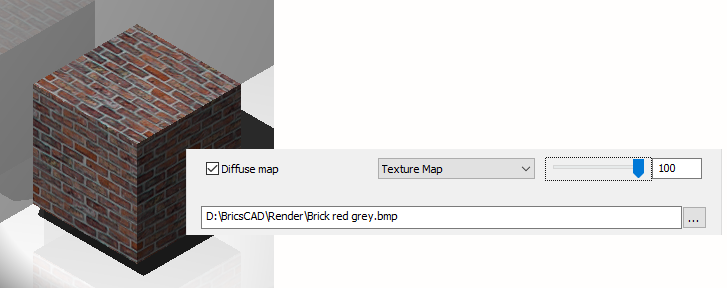
Diffuse Map |
Diffuse maps apply a texture to the surface of a material such as wood grains, bricks or tiles. Drag the slider to blend the texture map with the Color settings.
|
|
Transparency Map |
The selected Texture Map can be applied as Transparency Map or as Cutout Map. In the examples below, this image is used as transparency map and cutout map:
If Transparency Map is selected, the selected Texture Map image defines a transparency map. The image is recommended to be a grayscale image. White pixels will be invisible, black pixels will be opaque and gray pixels will be transparent. Notes:
Blend factor: the transparency values in the texture will approach the scalar Transparency setting as the blend factor approaches 0. This means that if the Blend factor is 100, then the transparency value will controlled completely by the Texture Map image. If the Blend factor is 0, the transparency texture will be completely ignored and the scalar Transparency value will be used.
If Cutout Map is selected, then the selected transparency map defines cutouts: parts of the objects will be fully visible and parts not visible at all, depending on the pixels of the selected image. The image is recommended to be a bitonal black-and-white image, without grays. White pixels are visible, and black pixels are invisible. The Cutout Map Inverted option inverts the effect: visible parts become invisible and vice versa. Notes:
|
|
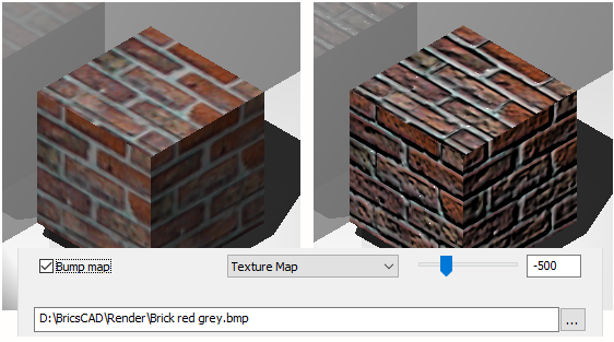
Bump Map |
Bump mapping is a technique for simulating bumps and wrinkles on the surface of an object. The result is an apparently bumpy surface although the surface of the underlying object is not modified. Blend factor range = -1000 / +1000
Left: Diffuse Map only; Right: Bump Map applied.
|
|
|
|
|
Map Transformation |
|
|
The texture map image is applied at a size of 1 drawing unit multiplied by the Width and Height factors. E.g. if the Width and Height factors or both set to 10, the size of the texture image is 10 x 10 drawing units. |
|
|
|
|
|
Offset |
Texture maps maps are tiled starting from the origin of the WCS. To adjust the tiling you can define an Offset X and Offset Y. The offsets are expressed in drawing units. |
|
Rotation |
Sets the rotation of the texture maps. Type the desired rotation in the Rotation field. |
Related Commands
MatBrowserOpen - opens the materials browser, which shows an overview of available high-resolution render materials.
MaterialMap - allows to adjust how a texture is mapped to regions, faces and faces of a 3D solid.
Render - calculates a photorealistic image of the 3D model.
Light - creates a new light in the drawing.
VisualStyles - creates and controls visual style definitions in the Drawing Explorer.
Explorer - opens the Drawing Explorer dialog box.
| © Menhirs NV. All rights reserved. |