Commands: BMBROWSER, DMUPDATE, DMFIX3D, DMCOINCIDENT3D, DMCONCENTRIC3D, DMPARALLEL3D, DMPERPENDICULAR3D, DMTANGENT3D, DMDISTANCE3D, DMRADIUS3D, DMANGLE3D
Variational Direct Modeling
BricsCAD offers powerful tools for parametric direct solid and surface modeling using geometric constraints solving (aka variational direct modeling). Solid and surface models can be modified by defining constraints between their elements (edges and faces), as soon as constraint is added BricsCAD automatically modifies the model accordingly, and these constraints are kept satisfied upon following modifications of the model. The key advantage of variational direct modeling is that all constraints are taken into account simultaneously and the model behavior does not depend on the constraints creation order. It allows you to parameterize any feature of the 3D model and to do not care about the model creation history.
Dimensional constraints allow controlling the dimensions of the model, when such constraint is introduced or the value of its parameter is changed BricsCAD automatically updates the solid and surface geometry to satisfy the constraint. For example, the dimensions of a box can be controlled by the parameters of three distance constraints applied to its opposite faces.
Constraints can be created using the 3D Constraints toolbar, the Parametric/3D Constraints menu or the Constraints command group in the Quad.
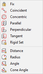
BricsCAD provides the following 3D constraints:
Geometrical constraints: Fix (![]() ), Coincident (
), Coincident (![]() ), Concentric (
), Concentric (![]() ), Parallel (
), Parallel (![]() ), Perpendicular (
), Perpendicular (![]() ), Tangent (
), Tangent (![]() ) and Rigid Set (
) and Rigid Set (![]() ).
).
Dimensional 3D constraints: Distance (![]() ) , Radius (
) , Radius (![]() ), Angle (
), Angle (![]() ), Cone Angle (
), Cone Angle (![]() ).
).
Mechanical Browser
The Mechanical Browser (![]() ) allows to navigate through
all the constraints in the model and to edit dimensional
constraints.
) allows to navigate through
all the constraints in the model and to edit dimensional
constraints.
See the BmBrowser command to learn more about the Mechanical Browser.
3D Constraints types
The following entities are supported for constraints creation:
Faces of ACIS solids and surfaces of planar, cylindrical, spherical, toroidal and conical geometry.
Linear and circular edges of ACIS solids and surfaces.
Lines, rayes, xlines, circles and arcs.
3D Constraints and Direct Modeling
3D Constraints are taken into account when direct modeling operations are applied. If there is a 3D constraint which fixes the placement of faces or edges this constraint will be preserved during Push/Pull, Move and Rotate operations. The dynamically presented result of the operation respects existing constraints as well.
If some faces or edges disappear in a direct modeling or in a Boolean solid editing operation 3D constraints applied to such entities are removed. However, if there is an exact correspondence between the initial faces and the faces obtained in a result of a Boolean operation 3D constraints are automatically applied to new entities.
If 3D constraints prevent modification of the model with a particular direct modeling operation (e.g. a Push/Pull operation applied to a face with a Fix constraint) the status line of the 3D Constraints Bar receives a No Solution status.
Depending on the value of the DMRECOGNIZE system variable, BricsCAD automatically recognizes geometrical relations between surfaces of a solid and preserves them during direct modeling operations (see Design Intent Recognition).
| © Menhirs NV. All rights reserved. |