BmBrowser
") Platinum
Platinum") Platinum
Platinum") Platinum
Platinum
Toggles the visibility of the Mechanical Browser panel.
Accessing the Command
command bar: bmbrowser
menu bar: Assembly | Mechanical
Browser
ribbon: Assembly | Tools | Mechanical
Browser 
toolbar: Assembly |
: bmbrowser
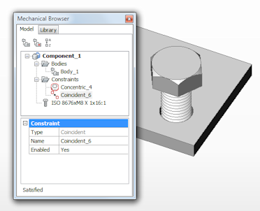
Displays a dialog box:
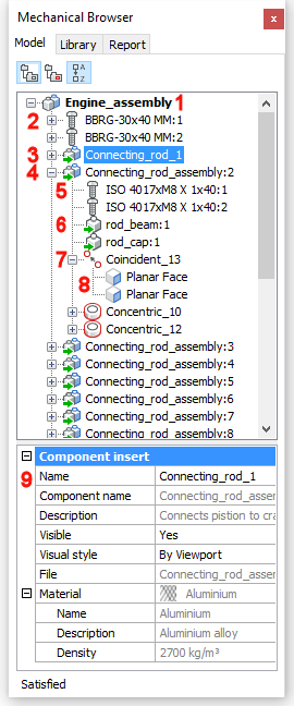
The Mechanical Browser allows navigation on the
hierarchy of mechanical components for the current drawing and
calling different commands for the inserts.
-
Component Name
-
Standard Part Component Insert (= block
reference)
-
Collapsed Component Insert (= external
reference)
-
Expanded Component Insert (= external
reference)
-
Standard Part Subcomponent Insert (= nested block
reference)
-
Subcomponent Insert (= nested external
reference)
-
3D geometrical constraint
-
3D features affected by the constraint
-
Properties of the selected item
- Name: name of
the component in the assembly (= internal name)
- Component
name: name of the component in the source file (= external
name)
- Description:
description of the component
- Visible:
controls the visibility of the component in the drawing
- Visual Style:
defines the visual style of the component (see also BmVStyle command).
- File: source
file of the component
- Material:
Material of the selected item, as defined in the Material definition of the source file.
If the Material definition of the
source file is set to <Inherit>, the material is copied from
the main component.
|
|
Icons
|
|
Rendered visual style
|
Wireframe visual style
|
Hidden
|
|
Component that does not contain subcomponents
|
 * *
|
 * *
|
 * *
|
|
Component that contains subcomponents
|
 * *
|
 * *
|
 * *
|
|
Standard Part Component
|

|

|

|
* External components have a green arrow added:  or
or 
Command Options
|
Option
|
Description
|
|
Model
|
|
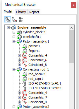
 Group by Entity Group by Entity
|
Groups 3d constraints by entity or mechanical
component they are applied to.
|
|
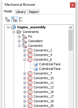
 Group by Type Group by Type
|
Groups mechanical components and 3d constraints
in separate trees.
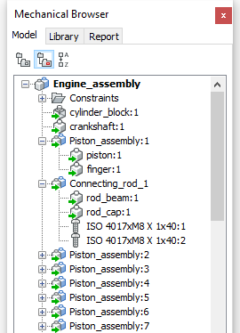
Groups 3d constraints by type.
Expand a constraint to see the 3D features
affected by the constraint.
 C C
|
|
 Sort Alphabetically Sort Alphabetically
|
When pressed ( ) the mechanical components and 3d constraints are sorted
alphabetically, ) the mechanical components and 3d constraints are sorted
alphabetically,
When depressed () the mechanical components and 3d constraints are listed in
the order they were added to the assembly.
|
|
|
|
Context Menus
|
|
Main Component context menu
|
Right click the main component name:
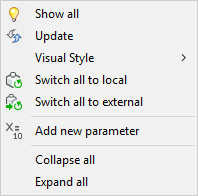
-
Show all: Displasy
all components in the assembly.
-
Update: Updates the
hierarchy of mechanical components for the current drawing in case
referenced drawing files of sub-components have been modified.
-
Visual Style: All by
Viewport: Applies the current Visual Style to all
components in the assembly (see the ShadeMode command).

-
Switch all to
local: Switches all components
to internal components (see the BmLocalize command).
-
Switch all to
external: Switches all components to external components
(see the BmExternalize
command).
-
Add new parameter:
Creates a new parameter in the assembly.
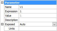
Name: Identifies the parameter. The parameter name can be
used in expressions of other parameters in the same
component.
Expression: Type a value or an expression.
Value: Displays the current value of the
parameter.
Description: Optional description of the
parameter.
Exposed: Defines whether the
parameter is visible and can be modified when the component is
inserted in an assembly.
Select the field, then click the down-arrow button and choose an
option. A new parameter gets the Auto
option by default.
Auto = the parameter is exposed only if it does not depend
on other parameters.
ON = the parameter is always exposed.
OFF = the parameter is never exposed.
Units: Sets
the dimension of the parameter: Linear, 2-dimensional or
3-dimensional.
Select the field, then click the down-arrow button and choose an
option.
-
Collapse all:
collapses the main component and all components and
subcomponents.
-
Expand all: expands
the main component and all components and subcomponents.
|
|
Component context menu
|
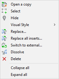
Right click a component name.
External components context menu (left), local
components context menu (right):
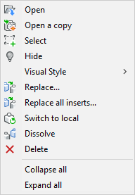 
-
Open: Opens the
referenced drawing (see the BmOpen
command).
-
Open a copy: Opens a
copy of a component insert as a new drawing (see the BmOpenCopy command).
-
Select: Selects the
component.
-
Hide ( ) / Show ( ) / Show ( ): Hides or shows the selected component. ): Hides or shows the selected component.
-
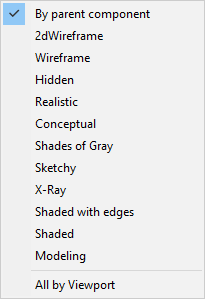
Visual Style: Displays the Visual Style menu. Visual Styles that are
saved in the current drawing are available.
-
By Viewport: Renders
the selected component according to the current viewport shademode
(see the ShadeMode command).
-
All by Viewport:
Renders all components according to the current viewport
shademode (see the ShadeMode
command).
-
Replace: Replaces a
component insert (see the BmReplace
command). Replacing a local insert turns it into an external
insert.
-
Replace all inserts:
Replaces all inserts that refer to the same source (see the
BmReplace command). Replacing local
inserts turns them into external inserts.
-
Switch to local:
Switches an external component to an internal component (see the
BmLocalize command).
-
Switch to external:
Switches an internal component to an external component (see the
BmExternalize command).
-
Dissolve: Dissolves
a mechanical component inserted in the current drawing (See the
BmDissolve command).
-
Delete: Removes the
selected component and its subcomponents from the assembly.
-
Collapse all:
collapses the main component and all components and
subcomponents.
-
Expand all: expands
the main component and all components and subcomponents.
|
|
Subcomponent context menu
|
Right click a component name:
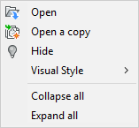
-
Open: Opens the
referenced drawing (see the BmOpen
command)
-
Open a copy: Opens a
copy of a component insert as a new drawing (see the BmOpenCopy command).
-
Hide () / Show (): Hides or shows the selected subcomponent.
-
Visual Style: See
Component Visual Style.
-
Collapse all:
collapses the main component and all components and
subcomponents.
-
Expand all: expands
the main component and all components and subcomponents.
|
|
Constraint context menu
|
Right click a constraint:
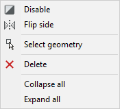
-
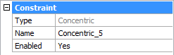
Disable/Enable: Toggles the selected
constraint ON/OFF.
The Enabled field in the Properties
grid is adjusted accordingly.
-
Flip side: Allows to change the
relative position of an entity (vectors normal of the selected
faces point in the same direction or in the opposite direction).
This option can be applied to Parallel, Coincident and Concentric constraints only and on condition the
constraint is applied to faces.
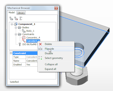 
-
Select geometry: Selects the
geometry, that is affected by the constraint, in the drawing.
-
Delete: Deletes the selected
constraint.
-
Collapse all:
collapses the main component and all components and
subcomponents.
-
Expand all: expands
the main component and all components and subcomponents.
|
|
|
|
Properties
|
|
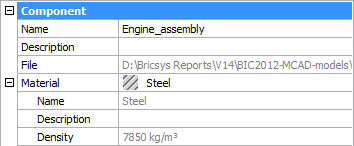
Main component properties
|
Click the main component name:
-
Name: Type a name
for the main component. By default the name of the main component
equals the file name.
-
Description:
Optional description of the main component.
-
File: Shows the path
and name of the dwg.
-
Material: Material of the main
component.
The Name, Density and the optional Description are defined in the Physical Materials dialog box.
Select the Material node, then do one
of the following:
-
Click the Browse
button ( ) to open the Physical Materials dialog and choose a material
in the Project or Library list. ) to open the Physical Materials dialog and choose a material
in the Project or Library list.
The Density property of the selected
material is used by the BmMassProp
command.
-
Click the Delete
button ( ). The Material field reads <Inherit>. ). The Material field reads <Inherit>.
When the component is inserted in an assembly, the Material definition is copied from the main
component of the assembly.
|
|
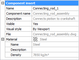
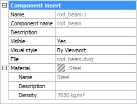
Component insert properties
|
Click the component name:
-
Name: Type a name
for the component. By default the name of the component equals the
source file name.
-
Component name: Name
of the component as defined in the source file.
-
Description:
Description of the component as defined in the source file.
-
Visible: Allows to
show or hide the component in the assembly.
Click the Visible field, then click
the down-arrow button and choose Yes
or No.
or
Double click the Visible field to
toggle the visibility of the component.
-
Visual stye: Allows
to control the visual style for the component. By default the
visual style is inherited from the viewport.
Click the Visual style field, then click the down-arrow button and
choose a visual style in the list.
-
File: Shows the path
and name of the referenced dwg.
-
Material: Shows the
material of the component.
If the in material the source file is set to <Inherit>, the
material is copied from the main component.
If the material is defined explicitly in the source file, this
material is used.
|
|
Subcomponent properties
|
Click the subcomponent name:
-
Name: Name of the
component as defined in the source file of the parent
component.
-
Component name: Name
of the component as defined in the source file.
-
Description:
Description of the component as defined in the source file.
-
Visible: Allows to
show or hide the component in the assembly.
Click the Visible field, then click
the down-arrow button and choose Yes
or No.
or
Double click the Visible field to
toggle the visibility of the component.
-
Visual stye: Allows
to control the visual style for the component. By default the
visual style is inherited from the viewport.
Click the Visual style field, then click the down-arrow button and
choose a visual style in the list.
-
File: Shows the path
and name of the referenced dwg.
-
Material: Shows the
material of the subcomponent.
If the in material the source file is set to <Inherit>, the
material is copied from the main component or the parent
component.
If the material is defined explicitly in the source file, this
material is used.
|
|
|
|
Selection Methods
|
|
Select a
component in the model.
|
The component highlights in the Mechanical Browser.
|
|
Click a
component in the Mechanical Browser
|
The component highlights in the drawing.
|
|
|
|
Library
|
|
Click the Library button to access
the standard parts library.
See the BmHardware
command.
|
|
|
|
Report
|
|
Some commands use the Report panel
to report the output; e.g. all SheetMetal (Sm*) commands,
DmAudit and
DmStitch.
The Report panel is used instead
of the command bar only if the BMREPORTPANEL
system variable is ON.
|
Related Commands
3dCompare - executes a
geometrical comparison between solids and surfaces in 2 drawing
files. The result is shown in a new drawing and reported in the
Mechanical Browser panel.
BmDependencies - lists all
files, containing component definitions inserted in the assembly,
in the command window.
BmExternalize - switches
internal components to external components.
BmHardware - inserts a
standard hardware part as a mechanical component in the current
drawing.
BmLocalize - switches external
components to internal components.
BmOpen - opens the component insert
drawing.
BmOpenCopy - opens a copy of a
component insert as a new drawing.
BmReplace - replaces a component
insert.
BmUpdate - reloads all referenced
components from external files and updates BOM tables.
-ToolPanel - allows to control
the display of tool panels, such as the Properties Bar, the Ribbon
or the Sheet Sets panel from the command line.
SmParametrize -
creates a consistent set of 3D constraints for a selected sheet
metal part.
|
© Menhirs NV. All rights reserved. |