Plotter Configuration
Command: PLOTTERMANAGER

Plotter configuration
Configurations for Windows system printers are stored in plotter
configuration files (.PC3 files). Unlike in AutoCAD®, PC3 plotter
configuration files in BricsCAD™ apply to Windows system printers
only.
In a plotter configuration file, you override one or more
settings of the system printers installed on your computer. You can
configure BricsCAD for many plotting/printing devices and keep
multiple configurations for each single device.
Each plotter configuration file contains information such
as:
-
The device driver and model
-
The output port to which the device is
connected
-
Various device-specific settings (not supported
on the Linux platform).
PC3 files are saved in the Plotconfig subfolder of your Roamable
root folder.
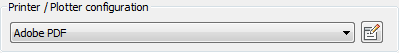
After creating a PC3 file, it is available in the list of
plotter configuration names in the Printer /
Plotter configuration list on the Print or Page Setup
dialog boxes.
To configure the built-in PDF
printer
-
Open the Print dialog.
-
Click the Printer/Plotter
configuration list button and choose Print As PDF.pc3 in the list.

-
Click the Edit Plotter
Configuration button ( ).
).
The Plotter Configuration Editor
dialog displays withe the Print As
PDF.pc3 configuration file loaded.
The default path for plotter configuration files (*.pc3) is:
C:\Users\<User_Name>\AppData\Roaming\Bricsys\BricsCAD\Vxx\en_US\PlotConfig

-
Click the Settings
tab on the Plotter Configuration
Editor dialog.

-
(Option) Edit the Graphics settings.
-
(Option) Execute the Scale
Calibration.
-
Click the Custom
Properties button.
The Print As PDF - Custom Properties
dialog displays.

-
(Option) Adjust the Output
quality and Layers support
settings.
-
Click the Manage Custom
sizes ... button.
-
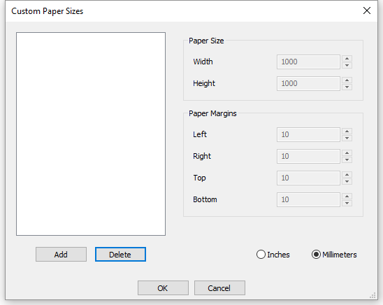
To create a custom paper size do the following:
- Click the
Add button.
A new paper size is added.
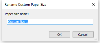
- Double
click the newly created papersize.
- Type a
name for the new paper size, then click the OK button.
- Define
Width an Height for the new paper size.
- Define the
Paper Margins.
Paper margins define the printable area of paper sheet.
If the DISPPAPERMARGINS
system variable is ON, dashed lines
indicate the paper margins on the paper sheet* in a layout.

* The paper sheet background displays if the DISPPAPERBKG
system variable is ON.
- Click the
OK button to create the custom paper
size.
-
Click the OK button
on each of the previously opened dialogs.
The custom paper size(s) can now be selected in the Paper Size list button.

To create a plotter
configuration file
- Choose Plotter
Manager... in the File menu,
then double click Create a Plotter
Configuration shortcut.
The Plotter Configuration
Editor dialog opens.
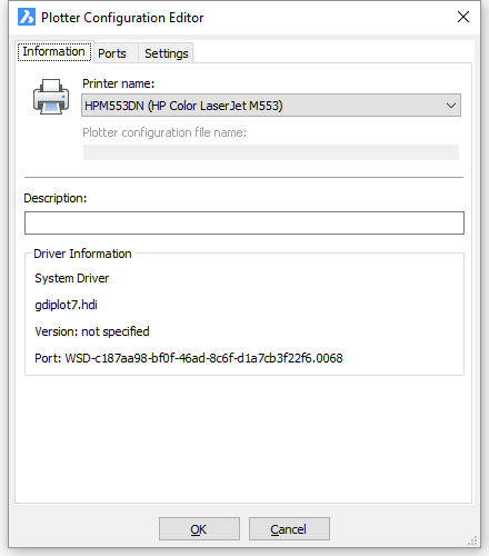
- In the Printer name
list, select the printer you want to create a plotter configuration
(PC3) for.
- Click the Settings
tab on the Plotter Configuration
Editor dialog.

- Click the Custom
Properties... button.
The <Selected Printer>
Properties dialog opens.
The layout of this dialog is different for each printer.
Custom Properties are not supported on the Linux platform.
- On the Properties
dialog of the selected printer, adjust the printer settings, then
click the OK button to confirm.
The <Selected Printer>
Properties dialog closes.
- Click the OK button
on the Plotter Configuration Editor
dialog.
The Save Plotter Configuration As
file dialog displays.

- (option) Adjust the PC3 file name.
The default name is <Selected
Printer>.pc3.
- Click the OK button
on the Changes to a Printer Configuration
File dialog.
The PC3 file is created.
|
NOTE
|
If you want to create multiple plotter
configurations for the same printer, you must adjust the default
name in step 7. If you accept the default name, the existing
plotter configuration will be overwritten.
|
To edit a plotter
configuration
- Do one of the following:
- Choose Page
Setup in the File menu.
- Type pagesetup
in the command bar, then press Enter.
- Select a plotter configuration (PC3) in the
Printer / Plotter configuration
list.
- Click the Edit Plotter
Configuration button () on the Print or Page Setup
dialogs.
The Plotter configuration editor
dialog opens.
- Proceed in the
Create a plotter configuration procedure starting from step
3.
|
NOTE
|
If you select a system printer in step 2, a new
plotter configuration is created for the selected printer.
When you click the Edit
Plotter Configuration button () in step 3, the Properties dialog of the selected printer opens
first.
After clicking the OK
button on the Properties dialog the
Plotter configuration editor dialog
opens.
You can then complete the
Create a plotter configuration procedure.
|
To assign a plotter
configuration
- Choose Model or the
Layout to which you want to assign a
specific plotter configuration file.
- Do one of the following:
- Choose Page
Setup in the File menu.
- Type pagesetup
in the command bar, then press Enter.
- Choose one of the following from the Printer / Plotter configuration list:
- A system printer
- A configuration file (PC3 file)
- None (uses Default)
- Click the OK
button.
|
NOTE
|
-
When BricsCAD™ cannot find the plotter
configuration file assigned to the drawing, it changes the
configuration file assigned to your drawing to None.
-
The None
printer device has its own set of paper sizes that can be stored in
the drawing very much the same as for any 'real' printer. If a
layout is opened and the stored printer is absent, the printer
switches to None while the
paper size is maintained. The missing printer and the previous
paper size are indicated upon opening the Print dialog. The previous paper size can be
saved in the drawing,
-
PREVIOUS PAPER SIZE: drawings created by
other parties are often set up for a printer that is not available
in your office. In such case, BricsCAD resets the printer device to
None , which results in using the
default printer. Instead of resetting the paper size to a default,
BricsCAD shows the Previous Paper size, in order to inform you
about the intended paper size and allow to choose a similar size on
any of the available printers.
|
|
© Menhirs NV. All rights reserved. |