![]() Platinum
Platinum![]() Platinum
Platinum![]() Platinum
Platinum
Creates one or more flanges to a sheet metal part by pulling one or more edges of an existing flange.
Accessing the Command
command bar: smflangeedge
menu bar: Sheet Metal | Create Edge Flange
toolbar: Sheet Metal | ![]()
: smflangeedge
Prompts you in the command bar:
Select one or more edges of existing flanges: (Select edges, then right click to proceed.)
Entities/subentities in set: 1
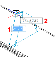
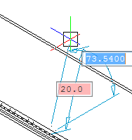
Position the end of the wall [Angle/Length/Taper angle/Width]: (Specify a point in 3D space or type a value in the dynamic height and angle fields)
Command Options
|
Option |
Description |
|
Define the height and angle of the flange by typing values in the dynamic height (1) and angle (2) entry fields:
Enter a value in the height field, then press the TAB key to jump to the angle field.
Type a value in the angle field, then do one of the following:
|
|
|
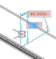
Allows to first define the angle, then the height of the flange. |
|
|
Allows to first define the length, then the angle of the flange. |
|
|
Allows to create a flange with one or two tapered side faces. Prompts you: Enter first taper angle [Back/Skip] <Skip>: Do one of the following:
Enter second taper angle [Back/Skip] <Skip>: Do one of the following:
Position the end of the wall [Angle/Length/Taper angle/Width]: Do one of the following;
|
|
|
By default the flange width equals the length of the selected edge. The Width option allows to define a different width. Prompts you: Enter first offset [Back/Skip] <Skip>: Do one of the following:
Enter second offset [Back/Skip] <Skip>: Do one of the following:
Position the end of the wall [Angle/Length/Taper angle/Width]: Do one of the following;
|
(*) The Taper Angle and Width options are not available if multiple edges are selected.
Related Commands
SmFlangeBase - creates a base (initial) flange of a sheet metal part from a closed planar profile.
SmFlangeConnect - closes gaps between two arbitrarily oriented flanges.
SmFlangeRotate - rotates a selected flange of a sheet metal part with automatic selection of the rotation axis depending on the design intent.
SmUnfold - creates an unfolded 2D or 3Drepresentation of a sheet metal part.
| Copyright © Menhirs NV - Alle Rechte vorbehalten. |