|
|
|
The same polyline drawn with PLINEGEN on (left) and off (right). |
You use different linetypes to differentiate the purpose of one line from another. A linetype consists of a repeating pattern of dots, dashes, or blank spaces. Linetypes determine the appearance of entities both on the screen and when printed. By default, every drawing has at least three linetypes: CONTINUOUS, BYLAYER and BYBLOCK. Your drawing may also contain an unlimited number of additional linetypes. Linetype definitions are saved in the drawing. New linetypes are either imported from other drawings or loaded from a linetype file (e.g. iso.lin or default.lin).
New entities are drawn using the current lineweight.
Entities which have a linetype BYLAYER adopt the linetype of their layer. This allows you to change the linetype of all such entities by adjusting the linetype of the layer.
Entities created using linetype BYBLOCK, are drawn as continuous lines until you include them into a block. The entities then inherit the block’s linetype setting when you insert the block into a drawing.
Non-continuous linetypes consist of lines, gaps and dots put together in a variety of patterns. In complex linetypes also text or shapes can be included. In the linetype definition the length of the lines and gaps are defined in drawing units. To display the linetype correctly it needs to be scaled to match the dimensions of your drawing. The linetype scaling factor is defined by the Linetype Scale (LTSCALE) system variable. Bricscad will always put a dash at the start and end of a line, polyline, arc or spline. The linetype pattern is also nicely centered, so that both ends of the entity look the same.
Because linetypes are affected by scale, paper space becomes a problem. A linetype scale that looks fine in model space is possibly going to look wrong in paper space. This problem is solved by the Paperspace Linetype Scale (PSLTSCALE) system variable. When set to 0 (zero) or OFF, scales linetypes are scaled the same in model space and in layouts, when set to 1 or ON, linetypes in layouts are drawn at the viewports scale.
Linetypes are normally generated from vertex to vertex. Polylines of which the vertices are very close together might be rendered as a continuous line, if the linetype pattern does not fit between two subsequent vertices. The Polyline Generation (PLINEGEN) system variable addresses this problem: when set to 1 or ON, the linetype is drawn from one end of the polyline to the other end, instead of from vertex to vertex.
|
|
|
The same polyline drawn with PLINEGEN on (left) and off (right). |
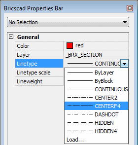
Do one of the following:
On the Bricscad
Properties Bar, select Linetype.
Make sure, no entity is selected.
Choose a linetype in the drop down list.

On the Entity Properties toolbar, click the down arrow next to the Linetype field, then choose a linetype in the drop down list.
Right click on the Linetype field in the Status Bar, then choose a linetype in the context menu.
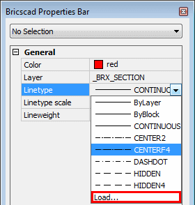
On the Bricscad
Properties Bar, select Linetype.
Make sure, no entity is selected.
Choose Load... at the end of the drop down list.

The Linetypes dialog opens.
(option) Click the File button on the Linetypes dialog to load a different linetype file (*.lin).
Select a linetype, then click the OK button.
The linetype is loaded.
|
NOTE |
The MEASUREMENT system variable controls the which linetype file will be used to copy a new linetype definition to the drawing. Default.lin is used if MEASUREMENT is OFF (Imperial), Iso.lin is used if MEASUREMENT is ON (Metric). The linetype files (*.lin) sit in the Support folder of the Roamable root folder. |
Setting the Entity Linetype Scale
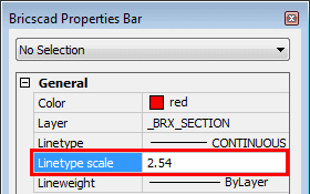
On the Bricscad
Properties Bar, select Linetype
scale.
Make sure, no entity is selected.
Type a new value in the Linetype scale field..

|
NOTE |
Linetype definitions in a *.lin file are expressed in drawing units: inches in default.lin, millimeters in iso.lin. If your drawing units are centimeters, set the linetype scale to 0.1 when using linetype definitions of iso.lin or 2.54 for linetype definitions of default.lin. |
Setting the Global Linetype Scale
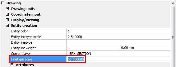
Choose Settings
in the Settings menu.
The Settings
dialog opens.
Select the Drawing settings category.
Expand the Entity Creation settings sub-category.
Select the Linetype
Scale setting (LTSCALE).

Type a new value in the Global Linetype Scale field, then press
Enter.
The drawing is regenerated.
Close the Settings
dialog.
|
NOTE |
When printing Model Space: set the Global Linetype Scale with respect to the plot scale. E.g. if you want to plot your drawing at 1/50, set the LTSCALE setting to 50. When printing a layout, do one of the following:
|
| © Menhirs NV. All rights reserved. |