![]()
Model Space, with floating viewports of layout PLAN
![]()
Paper Space of layout PLAN
Commands: MVIEW, MVSETUP, ALIGNSPACE and VPCLIP
The Mview command creates one or more viewports in layout tabs (short for "make viewports").
The MvSetup command creates multiple viewports; in model space the command creates a rectangle, representing a paper sheet with respect to a specified scale.
The AlignSpace command adjusts viewport angle, zoom factor and pan position based on alignment points specified in model space and paper space.
The Vpclip command clips viewports in layouts (short for "view port clipping").
In a layout you can create multiple viewports each of which displays a unique view of the entities created in model space. Each layout viewport functions as a window into your model space drawing. You can control the view, scale, and content of each layout viewport separately.
A layout viewport is created as a separate entity that you can copy, delete, move, scale, and stretch as you would any other drawing entity. You can snap to the viewport borders using entity snap. When you are working in model space with floating viewports (see Toggle between model space and paper space), click any layout viewport to make it the current viewport, and then add or modify model space entities in that viewport. Any changes you make in one layout viewport are immediately visible in the other viewports (if the other layout viewports are displaying that portion of the drawing). Zooming or panning in the current viewport affects only that viewport.
Each viewport has its own layer visibility settings. You can also turn off the display of the content of a viewport.
To preserve the scaling of a viewport you can lock the display. It is no longer possible to zoom or pan in a locked viewport.
Apart from viewports, you can add print-related entities in a paper space layout that are not essential to the model itself, such as keynotes, annotations, title blocks, etc. Such entities are part of a specific paper space layout and do not appear in other layouts or in model space.
When you are working in a layout, either Model Space or Paper Space is your current workspace. The Workspace field in the Status Bar indicates which workspace is current: M:<Layout Name> indicates you are working in Model Space, while P:<Layout Name> means Paper Space is the current workspace.
|
|
Model Space, with floating viewports of layout PLAN |
|
|
Paper Space of layout PLAN |
Displaying the paper sheet and the printable area
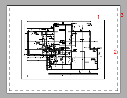
Viewport
Printable area.
The display of the printable area is controlled through the
DISPPAPERMARGINS
system variable.
Paper sheet.
The display of the paper sheet is controlled through the DISPPAPERBKG
system variable.
Click the appropriate layout tab at the bottom of the drawing window.
Do one of the following:
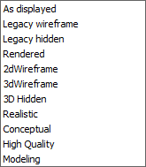
Click the Paper Space
Views tool button (![]() ) on the Views toolbar.
) on the Views toolbar.
Choose Paper Space Views in the Views menu.
Type mview at the command prompt, then press Enter.
The command bar reads: Viewports. ON/OFF/Fit/2/3/4/<First corner>:
A prompt menu opens:
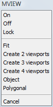
(option) To add 1 viewport. do one of the following:
Click to specify the first corner of the
viewport, then specify the opposite corner.
A single viewport which fits in the specified rectangle is
created.
Choose Fit to
view in the prompt menu or type F, then press Enter.
A single viewport which fits in the current drawing display window
is created.
(option) To create 2 viewports, do one of the following:
Choose Create 2 viewports in the prompt menu.
Type 2 in the command bar, then press Enter.
The command bar reads. Two viewports: Horizontal/<Vertical>:
|
Option |
Result |
|
Horizontal |
|
|
Vertical |
|
The command bar reads: Fit to screen/<First corner of bounding rectangle>:
Click to specify the first corner of the
bounding rectangle, then specify the opposite corner.
Two viewports which fit in the specified bounding rectangle are
created.
Choose Fit to
view in the prompt menu or type F, then press Enter.
Two viewports which fit in the current drawing display window are
created.
(option) To create 3 viewports. do one of the following:
Choose Create 3 viewports in the prompt menu.
Type 3 in the command bar, then press Enter.
The command bar reads. Three viewports: Horizontal/Vertical/Above/Below/Left/<Right>:
|
Option |
Result |
|
Horizontal |
|
|
Vertical |
|
|
Above |
|
|
Below |
|
|
Left |
|
|
Right |
|
The command bar reads: Fit to screen/<First corner of bounding rectangle>:
Click to specify the first corner of the
bounding rectangle, then specify the opposite corner.
Three viewports which fit in the specified bounding rectangle are
created.
Choose Fit to
view in the prompt menu or type F, then press Enter.
Three viewports which fit in the current drawing display
window are created.
(option) To create 4 viewports. do one of the following:
Choose Create 4 viewports in the prompt menu.
Type 4 in the command bar, then press Enter.
|
Option |
Result |
|
Create 4 viewports |
|
The command bar reads: Fit to screen/<First corner of bounding rectangle>:
Click to specify the first corner of the
bounding rectangle, then specify the opposite corner.
Four viewports which fit in the specified bounding rectangle are
created.
Choose Fit to
view in the prompt menu or type F, then press Enter.
Four viewports which fit in the current drawing display window are
created.
(option) To create a non-rectangular (clipped) viewport using an existing polyline or circle, do one of the following:
Choose Object in the prompt menu.
Type O in the command bar, then press Enter.
The command bar reads: Select Object to clip viewport.
Select a closed polyline or a circle in the layout.
(option) To create a non-rectangular (clipped) viewport, do one of the following:
Choose Polygonal in the prompt menu.
Type P in the command bar, then press Enter.
The command bar reads: Specify start point:
Specify the vertices of the non-rectangular viewport. Right click or press Enter to create the viewport.
|
NOTES |
|
Creating an array of layout viewports
Command: MVSETUP
Type mvsetup in the
command bar.
The command bar reads: Enter an option [Align/Create/Scale
viewports/Undo]:
Do one of the following:
Type C in the command bar, then press Enter.
Choose Create in the context menu.
The command bar reads: Enter an option [Delete objects/Create viewports/Undo] <Create>:
Press Enter to accept the default option.
The command bar reads: Enter choice for layout options <0-3>
[none(0)/single(1)/std. engineering(2)/array of viewports(3)]
<0>:
Do one of the following:
Type 3 in the command bar, then press Enter.
Choose Array of Viewports in the prompt menu.
The command bar reads: Specify first corner of bounding area for viewport(s):
Pick a point in the layout.
The command bar reads: Other corner of rectangle:
Pick a second point in the layout.
The command bar reads: Enter number of viewports in X direction
<1>:
Specify the number columns in the array.
The command bar reads: Enter number of viewports in Y direction
<1>:
Specify the number of rows in the array.
The command bar reads: Specify distance between viewports in X
direction <0.000>:
Do one of the following:
Press Enter, to create contiguous viewport columns.
Specify the horizontal distance between the viewports.
The command bar reads: Specify distance between viewports in Y direction <horizontal distance>:
Do one of the following:
Press Enter to set the vertical spacing equal to the horizontal spacing.
Type 0 (zero) to create contiguous viewport rows.
Specify the vertical spacing between the viewports.
The viewports are created.
Press Enter to conclude the command.
Command: VPCLIP
Type vpclip in the
command bar, then press Enter.
The command bar reads: Select viewport to clip:
Select the viewport.
The command bar reads: Polygonal <Select clipping
object>:
A prompt menu displays.

Do one of the following:
Select the clipping object.
Choose Polygonal in the prompt menu or type P, then press Enter.
You are prompted to draw a
polyline.
The viewport is clipped.
|
NOTE |
|
To remove the clipping boundary of a viewport
Command: VPCLIP
Type vpclip in the
command bar, then press Enter.
The command bar reads: Select viewport to clip:
Select a clipped viewport.
The command bar reads: Polygonal/Delete<Select clipping
entity>:
Do one of the following:
Type D, then press Enter.
Choose Delete in the prompt menu.
Select the viewport.
If you select a clipped viewport, click the Selected Entities button on top of the
Properties Bar, then choose
Viewport in the list.
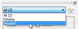
The viewport properties display in the Properties Bar.
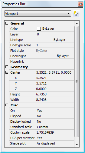
If you select a clipped viewport, click the Selected Entities button on top of the Properties Bar, then click Viewport in the list.
Click the settings field of a property to modify.
|
Name |
Description |
|
Center |
XYZ coordinates of the center point of the viewport. To specify the center of the viewport graphically, drag the center handle of the viewport. |
|
Height (*) |
Height of the viewport in drawing units. To specify the height of the viewport graphically, drag the top or bottom handle of the viewport. |
|
Width (*) |
Width of the viewport in drawing units. To specify the width of the viewport graphically, drag the left or right handle of the viewport. |
|
On |
Controls the display of the content of the viewport. |
|
Clipped |
Allows to create non-rectangular viewports. |
|
Display locked |
Locks the scaling of the viewport content to preserve the scaling factor. |
|
Standard scale (*) |
Lets you choose a standard scaling factor. The SCALELISTEDIT command allows to edit the available scales in the current drawing. |
|
Custom scale (*) |
Lets you define the scaling factor in a decimal format. Displays the current scaling factor. |
|
UCS per viewport |
If Yes, lets you define a UCS for this viewport. |
|
Defines how the viewport will be plotted. The options are:
|
(*) You must choose the width and height of a paperspace viewport with respect to the viewport scale.
Navigating in a paper space layout
View manipulation commands, such as zoom, pan and view manipulation using the mouse, act slightly different in a paper space layout compared to model space (with tiled viewports).
If you are working in paper space (no viewport selected), view manipulation commands act on the complete paper space layout.
If you are working in a viewport (model space with floating viewports), view manipulation commands act on the active viewport only. Except if the display of the current viewport is locked, then the view manipulation commands act on the complete paper space layout.
|
NOTE |
It is not possible to rotate the display of a paper space layout. View Rotate commands are available in viewports of which the display is not locked only. |
Setting the layer visibility in a viewport
Do one of the following:
If Paper Space is the current workspace: double click inside the viewport to make it the current viewport.
If Model Space with floating viewports is the current workspace: click inside the viewport to make it the current viewport.
Do one of the following.
Click the Layers... tool button on the Settings toolbar.
Choose Layers... in the Settings menu.
Type layer in the command bar, then press Enter.
The Drawing Explorer - Layers window opens.
In the Curr. VP (Current Viewport) column:
click the frozen icon (![]() ) of the layer(s) you want to thaw.
) of the layer(s) you want to thaw.
click the thawed icon (![]() ) of the layer(s) you want to freeze.
) of the layer(s) you want to freeze.
Close the Drawing Explorer - Layers window.
(option) Repeat steps 1 through 4 to set the layer visibility in another viewport.
|
NOTE |
Use the Viewports / Vpfreeze option of the LAYOFF and LAYFRZ commands to freeze layers in a viewport by clicking entities. |
Setting the scale of a viewport
Make sure the Plot Scale property of the layout is set correctly.
Switch to paperspace.
(See Toggle
between model space and paper space)
Click the viewport border.
The viewport properties display in the BricsCAD Properties
Bar.
Do one of the following:
Choose a scale in the Standard scale list.
Type a scaling factor in the Custom scale field.
(option) If necessary, adjust the size of the viewport to the new scale.
(option) Set the Display Locked property to Yes.
|
NOTE |
In a locked viewport it is impossible to:
|
Setting the scale of a selection of viewports
Command: MVSETUP
Make sure the Plot Scale property of the layout is set correctly.
Type mvsetup in the
command bar.
The command bar reads: Enter an option [Align/Create/Scale
viewports/Undo]:
Do one of the following:
Type S in the command bar, then press Enter.
Choose Scale viewports in the prompt menu.
The command bar reads: Select entities
Select the viewports.
Press Enter or right click to stop selecting
viewports.
The command bar reads: Set the scaling mode of viewports:
Interactively/<Uniform>:
Do one of the following:
Press Enter to set the scale of the selected
viewports uniformly.
The command bar reads: Enter the number of paper space units
<1.0>:
Press Enter to accept the number of paper
space units.
The command bar reads: Enter the number of model space units
<1.0>:
Type the desired scaling factor: e.g. 50 to apply a 1/50 scale.
Press Enter to apply the scale to all selected viewports.
Press Enter to conclude the command.
Choose Interactively in the prompt menu or type
I, then press Enter.
The first viewport in the selection set highlights.
The command bar reads: Enter the number of paper space units
<1.0>:
Press Enter to accept the number of paper
space units.
The command bar reads: Enter the number of model space units
<1.0>:
Type the desired scaling factor: e.g. 50 to apply a 1/50 scale.
Press Enter to apply the scale to the
viewport.
The next viewport highlights.
The command bar reads: Enter the number of paper space units
<1.0>:
Repeat the previous steps for each of the selected viewports.
Press Enter to conclude the command.
To rotate the display in a viewport
The display of a layout viewport can be rotated only if the display of the viewport is not locked.
If the VPROTATEASSOC system variable is ON, the ROTATE command rotates the content of a viewport over a specified angle.
The Align > Rotate option of the MVSETUP command rotates the content of a viewport relative to the X-axis of the world coordinate system (WCS).
Select the viewport, then right click and choose
2D Rotate in the context menu.
The command bar reads: Rotation point.
Use the Center ( )
entity snap to select the center point of the viewport as the
rotation point.
The command bar reads: Copy/Base angle/<Rotation angle>
<0>:
Type the rotation angle, then press Enter.
The content of the viewport is rotated over the specified angle.
Type mvsetup in the
command bar.
The command bar reads: Enter an option [Align/Create/Scale
viewports/Undo]:
Do on of the following:
Type A in the command bar, then press Enter.
Choose Align in the prompt menu.
The command bar reads: Enter an option [Angled/Horizontal alignment/Vertical alignment/Rotate view/Undo]:
Do one of the following:
Type R in the command bar, then press Enter.
Choose Rotate view in the prompt menu.
The command bar reads: Specify basepoint in the viewport to be rotate:
Specify the rotation point in the viewport.
The command bar reads: Specify rotation angle:
Type the rotation angle in the command bar, then
press Enter.
The viewport display is rotated over the specified angle with
respect to the X-axis of the WCS.
|
NOTE |
Type 0 (zero) in the final step of the above procedure to undo the rotation of the viewport display. |
Command: MVSETUP
Type mvsetup in the
command bar.
The command bar reads: Enter an option [Align/Create/Scale
viewports/Undo]:
Do on of the following:
Type A in the command bar, then press Enter.
Choose Align in the prompt menu.
The command bar reads: Enter an option [Angled/Horizontal alignment/Vertical alignment/Rotate view/Undo]:
Do one of the following:
To align two viewports horizontally:
Choose Horizontal
alignment in the context menu or type H in the command bar, then press Enter.
The command bar reads: Specify basepoint:
Pick a point in the reference viewport.
The command bar reads: Specify point in viewport to be panned:
Pick a point in the viewport to be
aligned.
The display in the viewport is moved vertically to align the two
points horizontally.
To align two viewports vertically:
Choose Vertical
alignment in the context menu or type V in the command bar, then press Enter.
The command bar reads: Specify basepoint:
Pick a point in the reference viewport.
The command bar reads: Specify point in viewport to be panned:
Pick a point in the viewport to be
aligned.
The display in the viewport is moved horizontally to align the two
points vertically.
To align model space and paper space points
Command: ALIGNSPACE
Type alignspace in
the command bar, then press Enter.
The command bar reads: First alignment point in Model space:
Click inside a layout viewport, then pick a
point.
The command bar reads: Second alignment point in Model space or
<Return> for none:
Right click or press Enter.
The command bar reads: Alignment point in Paper space:
Pick a point in the layout.
The command bar reads: Activate the viewport which will be used for
alignment.
Click inside the viewport you want to align.
Right click or press Enter to confirm.
The display in the selected viewport is moved to make the two
points coincident.
Type alignspace in
the command bar, then press Enter.
The command bar reads: First alignment point in Model space:
Click inside a layout viewport, then pick a
point.
The command bar reads: Second alignment point in Model space or
<Return> for none:
Pick a second point in the layout viewport.
The command bar reads: First alignment point in Paper space:
Pick a point in the layout.
The command bar reads: Second alignment point in Paper space:
Pick a second point in the layout.
The command bar reads: Activate the viewport which will be used for
alignment.
Click inside the viewport you want to align.
Right click or press Enter to confirm.
The display in the selected viewport is moved, rotated and/or
scaled to make the points two by two coincident.
| © Menhirs NV. All rights reserved. |