![]()
![]()
![]()
Creates and sets named views through the Drawing Explorer.
Accessing the Command
command bar: view
alias: ddview, v, expviews
menu bar: Tools | Drawing Explorer | Views
: view
Displays the Views section of the Drawing Explorer dialog box:
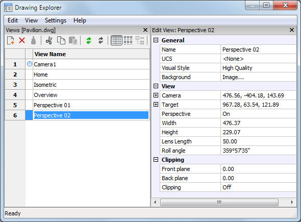
Create or select named views, and then click X.
Press F1 to access help.
Command Options
|
Option |
Description |
|
Designates the current view. |
|
|
Creates new named views; clears the dialog box and then prompts you: View: ? to list saved views/Save/Window - enter an option.
Lists the names of views saved in this drawing; prompts you: View(s) to list <List all views> - enter a name or press Enter for all. BricsCAD reports like this: Name of view: NewView1 Space: Model Height of view: 10.0830 Center of view: X= 0.0000 Y= 0.0000 Press F2 to see the Prompt History window.
Saves the current viewpoint as the named view. Returns to the Drawing Explorer.
Saves a windowed area as the view; prompts you: First corner of view window - pick a point, or enter x,y coordinates. Opposite corner - pick another point, or enter x,y coordinates. Returns to the Drawing Explorer. |
|
|
Erases the named view from the drawing without warning. |
|
|
Regenerates the current viewport. |
|
|
Toggles the regeneration of the current viewport after each change ON/OFF. |
|
|
|
|
|
General |
|
|
|
Specifies the name of the view. Click to edit. |
|
Assigns a saved UCS to the view (see the Ucs and ExpUcs commands. |
|
|
Sets the visual style (see the VisualStyles command). |
|
|
|
Sets the background image for rendered views. Select the field, then select an option: Solid, Gradient or Image (Sun & Sky option is not implemented yet).
Sets the background to a solid color. Click the Color
button to open the Select Color dialog,
Sets the background to a gradient color. Define the rotation angle in the Rotate field. Choose either Two or Three colors. Click the Top,
Middle and Bottom Color buttons to open the Select Color
dialog,
Click the Browse
button, then select an image file. Click the Align
option button to set the alignment of the image.
|
|
|
|
|
View |
|
|
Specifies the camera point of the view in x,y,z coordinates in visual perspective mode.. Click to edit. |
|
|
Specifies the target point of the view in x,y,z coordinates in visual perspective mode.. Click to edit. |
|
|
Sets the Perspective property of a view. A camera glyph displays in the drawing for perspective views (see the Camera command). |
|
|
Specifies the width of the view in current units. Click to edit. |
|
|
Specifies the height of the view in current units. Click to edit. |
|
|
Defines the lens length of the camera. Click to edit. |
|
|
Defines the rotation of the camera around the view axis. Click to edit. |
|
|
|
|
|
Clipping |
|
|
Sets the distance between the target point and the back clipping plane. Click to edit. |
|
|
Sets the distance between the target point and the front clipping plane. Click to edit. |
|
|
Defines whether the front and/or back clipping planes are active or not. Click the down arrow button, then choose an option:
|
|
Procedures
Related Commands
-View - controls named views through the command bar.
Camera - creates perspective views.
Print - plots named views.
Rename - renames views through the Drawing Explorer.
Zoom - utilizes the Previous option to show the previous view.
Explorer - Opens the Drawing Explorer dialog box.
| © Menhirs NV. All rights reserved. |