![]() Pro, Platinum
Pro, Platinum![]() Pro, Platinum
Pro, Platinum![]() Pro, Platinum
Pro, Platinum
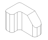
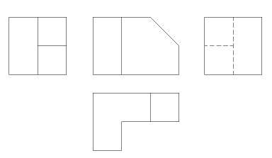
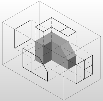
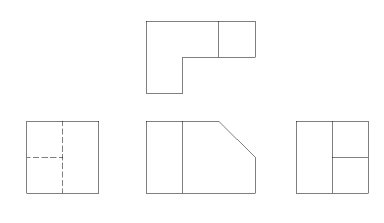
Generates associative orthographic and standard isometric views of a 3D solid model in a paper space layout.
Accessing the Command
command bar: viewbase
menu bar: View| Generate Drawing Views
toolbar: View | Generated
Views | ![]()
: viewbase
Prompts you in the command bar:
Select objects or [Entire model/preseTs] <Entire model>: (Select one or more 3D solids or press Enter to select the Entire model or select the Presets option.)
Enter new or existing layout name to make current <Layout>: (Press Enter to accept the current layout or type the name of a new or existing layout.)
Select position for base view [Scale/Tangent edges/Orientation/Projection type/Isometric style/Exit <Exit>: (Click to position the main view or right click to abort the command.)
Select position for projected view [Exit] <Exit>: (Move the cursor left, right, above or below the base view to create an orthographic view; move the cursor diagonally with respect to the base view to create an isometric view; click to position the view or right click to stop placing views; or continue until the final view is inserted.)
Command Options
|
Option |
Description |
|
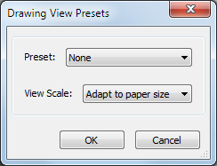
Allows to select a preset, which controls the number of generated drawing views and their placement in the layout. The selected preset is saved through the DRAWINGVIEWPRESET system variable. Displays a dialog box:
Click the Preset button to select a preset. The options are:
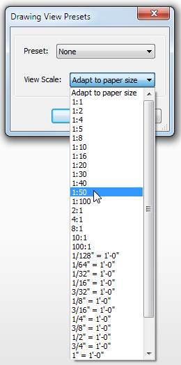
Click the View Scale button, then select a scale. The scale list can be edited by the SCALELISTEDIT command.
|
|
|
Sets the Scale property of the paper space viewports for the various views. Prompts you: Adjust view scale [fit 4 views/9 views/5 views/10 views/Standard scales/Custom/Exit] <fit 4 views>: Select an option:
(*) The Front view (base view) is defined by the Orientation option. |
|
|
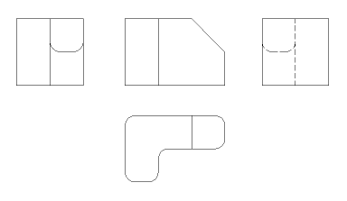
Defines whether tangent edges between tangent faces display or not. Prompts you: Enable tangent edges on basic views? [Yes/No/Exit] <No>: NO:
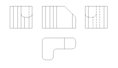
Yes: Tangent edges always display in isometric views:
|
|
|
Defines the main view. Rotates the 3D model so that the main view is projected on the vertical projection plane (V.P.).
Prompts you: Select orientation [Front/bAck/Left/Right/Top/Bottom/Exit] <Front>: Select the base view. |
|
|
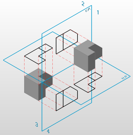
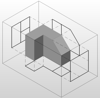
Defines the layout of the views. Prompts you: Select the projection type [First angle/Third angle/Exit] <First angle>: First Angle or European projection:
Third Angle or American projection:
|
|
|
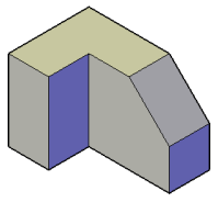
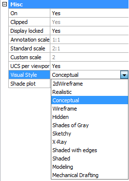
Defines the style for the isometric views: rendered 3D view or 2D drawing. Prompts you: Enable conceptual visual style for isometric views? [Yes/No/Exit] <No>:
|
|
|
Concludes the command. |
Related Commands
Flatshot - creates a hidden line representation of 3D solids in model space.
MvSetup - creates multiple paper space viewports; aligns, rotates and scales paper space viewports. In model space the command creates a rectangle, representing a paper sheet with respect to a specified scale.
Solprof - creates a hidden line representation of 3D solids in a layout viewport.
ViewExport - exports the content of drawing views and sections obtained by VIEWBASE and VIEWSECTION to the Model Space of the drawing.
ViewDetail - creates a detail view of a portion of a standard generated drawing at a larger scale.
ViewDetailStyle - allows to specify the visual format of detail views and detail symbols.
ViewEdit - allows changing the scale and the hidden line visibility of drawing views.
ViewExport - Exports the content of drawing views obtained by VIEWBASE and VIEWSECTION to the Model Space of the drawing or to a new drawing.
ViewProj - generates additional projected views from an existing drawing view.
ViewSection - creates a cross section view based on a standard drawing view generated by the VIEWBASE command in a paper space layout.
ViewSectionStyle - allows to specify the visual format of section views and section lines.
ViewUpdate - updates a selection of drawing views or sections when VIEWUPDATEAUTO = 0.
| © Menhirs NV. All rights reserved. |