Digitizing Tablet
Command: TABLET
The Tablet command configures and calibrates a digitizing
tablet and toggles tablet mode.
This command requires that Wintab32.dll from Wacom
Technology, Corp. be installed on the computer. Download
Wintab32.dll from the internet, then place the file in your system
directory: C:\Windows\System32.
A digitizing
tablet, also called a graphics tablet,
a graphics pad or drawing tablet, is a
computer input device that allows you to hand-draw images and
graphics, similar to the way one draws images with a pencil and
paper. In a CAD program a digitizing tablet can be used to
trace paper drawings into a drawing file or to launch drawing
commands from a digitizing tablet
overlay.
To use
a digitizing tablet in BricsCAD
In order to prepare BricsCAD for using a digitizing tablet do
the following:
-
Install the appropriate driver for your tablet.
-
Make sure Wintab32.dll exists in
C:\Windows\System32.
-
Download the tablet
overlay and CUI files.
-
Print the BricsCAD tablet overlay.
-
Load
the overlay CUI file.
-
Start BricsCAD, then initialize the tablet.
-
Configure the tablet:
part of the tablet surface is used as the menu area, another part
as the screen pointing area.
-
Calibrate the tablet: a
calibrated tablet can be used to trace the geometry of a paper
drawing or image into a drawing.
To download the tablet overlay and CUI
files
-
Go to the BricsCAD
Documentation and Tools page on the Bricsys website.
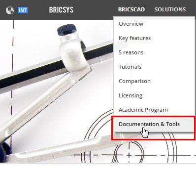
- Scroll down to the bottom of the page and click
the DOWNLOAD button under
Tablet overlay.
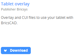
- Save the tablet.zip
file.
The zip-file contains the following files:
- overlay.png: an image of the tablet overlay
- overlay(A3).pdf: to print the tablet overlay on a
A3 paper size.
- overlay(cm).dwg: a DWG in which the overlay.png is attached as an image.
The drawing contains two layouts to print the overlay using decimal
units.
- overlay(inch).dwg: a DWG in which the
overlay.png is attached as an
image.
The drawing contains two layouts to print the overlay using
imperial units.
- tablet.cui: a
partial cui file to be used with a tablet.
- tablet(acadLike).cui: an AutoCAD-like partial cui
file to be used with a tablet.
Please make sure the overlay.png image file is extracted to the same
folder as the DWG's.
To load the overlay CUI file
- Extract the overlay CUI files to the Support folder of the roamable root folder (see BricsCAD
User Files).
E.g. C:\Documents and Settings\<user name>\Application
Data\Bricsys\BricsCAD\V...\en_US\Support on Windows XP;
C:\Users\<user
name>\AppData\Roaming\Bricsys\BricsCAD\V...\en_US\Support on
Windows Vista and Windows 7.
- Load Tablet.cui as a
partial CUI (see
To load a partial CUI file).
The next time you start BricsCAD, Tablet.cui will be loaded automatically.
|
NOTE
|
It might be necessary to repeat the above procedure after
upgrading BricsCAD.
|
To
switch the tablet ON / OFF
Do one of the following:
- Click the TABLET field in the
Status Bar.
- Press the F4
function key to toggle the tablet mode.
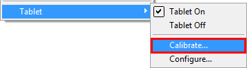
- Choose Tablet
On or Tablet Off in the
Settings menu.
- Type tablet in
the command bar, press Enter, then type ON or OFF ;
or
click ON or OFF in the prompt box.
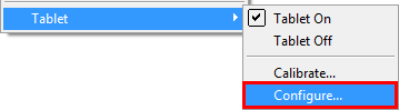
To configure the tablet
- Do one of the following:
- Choose Tablet
in the Settings menu, then
choose Configure... in the flyout
menu.
 +
+
- Type tablet in the command bar and press
Enter.
The command bar reads: Tablet:
ON/OFF/CALibrate/ConFiGure/<On>:
a prompt menu displays:
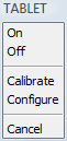
Type cfg in the command bar and press
Enter or choose Configure in the
prompt menu.
The command bar reads: Do you want to align the
tablet overlay? Yes/No/<No>:
- Type Y in the
command bar and press Enter or choose Yes in the prompt menu.
The command bar reads: Digitize upper left corner of the
overlay:
- Click on the mark in the upper left corner (1) of
the digitizing tablet overlay.
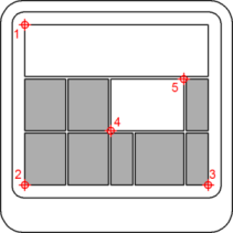
The command bar reads: Digitize the lower left corner of the
overlay.
- Click on the mark in the lower left corner (2)
of the digitizing tablet
overlay.
The command bar reads: Digitize the lower right corner of the
overlay.
- Click on the mark in the lower right corner (3)
of the digitizing tablet
overlay.
The command bar reads: Digitize the lower left corner of the screen
pointing area:
- Click on the mark at position (4) on the of the
digitizing tablet overlay.
The command bar reads: Digitize the upper right corner of the
screen pointing area:
- Click on the mark at position (5) on the of the
digitizing tablet overlay.
The command bar reads: Tablet configured.
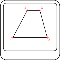
To calibrate the tablet
To calibrate the digitizing tablet you must specify at least two
points. The more additional points you specify, the more accurate
the digitizing process. Additional points are particularly
recommended when digitizing a non-orthogonal image, such as an
aerial photograph.
- Do one of the following:
- Choose Tablet
in the Settings menu, then
choose Calibrate... in the flyout
menu.
 +
+
- Type tablet in the command bar and press
Enter.
The command bar reads: Tablet:
ON/OFF/CALibrate/ConFiGure/<On>:
a prompt menu displays:
Type cal in the command bar and press
Enter or choose Calibrate in the
prompt menu.
The command bar reads: Digitize point #1:
- Click a point on the digitizing tablet .
The command bar reads: Enter coordinates for point #1:
- Do one of the following:
- Click a point in the BricsCAD drawing
window.
- Enter the coordinates (x,y) in the command
bar.
The command bar reads: Digitize point #2:
- Repeat step 3 to specify the following calibration
point.
The command bar reads: Digitize point #3 (or ENTER to end):
- Do one of the following:
- Repeat step 4 to specify an additional
calibration point.
(You can specify up to 10 calibration points).
- Press Enter to conclude the calibration
process.
The command bar reads:
if 2 calibration points are specified: Tablet calibrated.
if 3 or more than 4 calibration points are specified: Select
transformation type Orthogonal/Affine:
if 4 calibration points are specified: Select transformation type
Orthogonal/Affine/Projective:
- Select the transformation type.
Transformation refers to the calculation of the points on the
screen that correspond to points you digitize on the tablet.
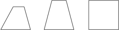
Orthogonal (left): To be
used with accurate paper drawings. Orthogonal transformation
maintains all angles and preserves relative distances. If only two
calibration points are specified orthogonal transformation is
generated automatically.
Affine (middle):
Maintains parallel lines, but not necessarily the angles between
intersecting lines.
Projective (right): Does
not maintain parallel lines, nor angles.
|
© Menhirs NV. All rights reserved. |