![]() BIM
BIM![]() BIM
BIM![]() BIM
BIM
Creates a BIM section entity.
Accessing the Command
command bar: bimsection
menu bar: BIM | Define Section
toolbar: BIM | ![]() or
or ![]() (Detail Section)
(Detail Section)
: bimsection
The Section Tracker is attached to the cursor.
![]()
The section plane (1) lies in the XY-plane of the current coordinate system (WCS or UCS). The view direction (2) is in the negative Z-direction of the current coordinate system.
If Dynamic UCS (UCSDETECT) is ON, the section plane aligns to the face of a 3D solid under the cursor.
Prompts you in the command bar:
Select a point to place section or [Detail/Scale]: (Specify a point.)
The section plane displays dynamically parallel to UCS XY-plane, through the cursor position.
The display of the 3D geometry is clipped.
Specify distance: (Type a distance* or specify a point.)
The section plane is defined through the point or at the specified offset from the first point.
* It is recommended to have Dynamic Dimensions (DYN) active, which allows to type the distance in the dynamic entry field.
The section line is parallel to the X-axis of the UCS or dynamic UCS and through the point at the specified offset from the first point.
Only the section line and the callouts of a BIM Section entity display. When highlighted or selected the section plane, section boundary and/or section volume display.
The Clip Display property of the BIM Section entity is enabled by default. Double click the section line or a callout of a section to toggle Clip Display on/off. Multiple sections can have Clip Display on simultaneously.
BIM section entities are created on the current layer. It is recommended to create a dedicated layer for BIM sections. The BIM_Sections layer is created automatically along the first BIM section entity.
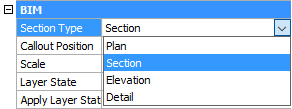
Horizontal sections get the Plan section type, other sections get the Section section type, unless no geometry is cut by the section plane, then the section type is Elevation.
The section type can be edited in the Section Type field on the Properties Bar.
Command Options
|
Option |
Description |
|
Sets the Scale property of the viewport in the drawing file created by the BIMSECTIONUPDATE command. The default Scale is saved through the SectionScale user preference. Prompts you: Specify a scale for the viewport with the section result (0.000001 - 1000000.000000) <0.020000>: Do one of the following:
|
|
|
Creates a Detail section type. Prompts you: Select first corner of the volume box base rectangle or [Based on an existing section/Scale]: Specify a point, or choose an option. Select the oppersite corner of volume box base rectangle: Do one of the following:
Select the height of volume box: Do one of the following:
|
|
|
Creates a Detail section type based on an existing section. The base rectangle of the detail section will be parallel to the section plane of the selected section. Prompts you: Select an existing section plane as base: Select a Bim section. Select first corner of the volume box base rectangle or [Based on an existing section/Scale]: Specify a point, or choose an option. Select the oppersite corner of volume box base rectangle: Do one of the following:
Select the height of volume box: Do one of the following:
|
Procedures
General procedure to create a BIM section entity
Defining the BIM Section entity properties
To create a 2D isometric drawing
Turning a section plane into a BIM section entity
Creating a jogged BIM section entity
Grips Editing
BIM Section entities can be edited through grips.
Select the entity. A section entity in Plane state has 3 grips.
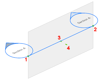
Start grip: allows to move the section and the position of the Start callout..
End grip: allows to modify the orientation of the section and the position of the End callout.
Center Grip: allows to move the section and the position of the Mid callout.
Click the arrow to flip the view direction.
In Boundary state, section entities have five more grips.
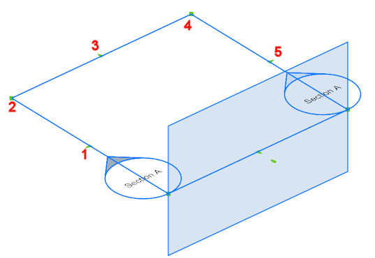
Midpoint grip: allows to move the section entity.
Corner grip: allows to deform the section boundary/volume.
Midpoint grip: allows to stretch the section boundary/volume.
Corner grip: allows to deform the section boundary/volume.
Midpoint grip: allows to stretch the section boundary/volume.
In Volume state, section entities have two more grips, compared to the boundary state..
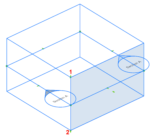
Allows to move the top plane of the section entity.
Allows to move the bottom plane of the section entity.
Related Commands
BimPatch - allows to replace part of a generated section.
BimSectionUpdate - exports or updates the result of a BIM section in a drawing.
ClipDisplay - toggles the Clip Display property of a section plane or a BIM section entity.
Section - creates section planes of 3D solids; the results are region entities.
SectionPlane - creates a section entity that creates sections of 3D solids.
SectionPlaneSettings - defines the properties of a section plane entity in the Drawing Explorer - Section Planes dialog.
| © Menhirs NV. All rights reserved. |