![]() Sheet Metal
Sheet Metal![]() Sheet Metal
Sheet Metal![]() Sheet Metal
Sheet Metal
Creates a consistent set of 3D constraints for a selected sheet metal part.
The command takes into account implicit constraints from the sheet metal features and ensures that the constraint system is not overdefined. Editing the parameter allows to obtain a series of similar sheet metal parts with different dimensions. Please notice that for the best results, the sheet metal part should have a complete set of features, including flanges, bends, junctions and bend and corner reliefs.
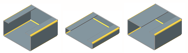
Example of a fully parametrized sheet metal part (left) and different sets of parameters applied (center and right):
Accessing the Command
command bar: smparametrize
menu bar: Sheet Metal | Parametrize
toolbar: Sheet Metal | ![]()
ribbon: Sheet Metal | 3D Constraints |
![]()
: smparametrize
Prompts you in the command bar:
Select sheet metal part for automatic parametrization: (Select a sheet metal part.)
Depending on the value of BMREPORTPANEL BricsCAD prints a message in the command bar or in the Mechanical Browser / Report panel:
xx distance constraints and xx coincident constraints were created.
The constraints can be edited in the Mechanical Browser panel.
Command Options
No options.
Related Commands
BmBrowser - toggles the visibility of the Mechanical Browser panel.
SmConvert - automatically recognizes flanges and bends in a 3D solid.
SmFlangeBase - creates a base (initial) flange of a sheet metal part from a closed 2D entity.
SmFlangeConnect - closes gaps between two arbitrarily oriented flanges.
SmFlangeEdge - creates one or more flanges to a sheet metal part by pulling one or more edges of an existing flange.
SmReliefCreate - makes proper corner and bend reliefs.
| © Menhirs NV. All rights reserved. |