![]()
![]()
![]()
Allows to specify the visual format of section views and section lines.
Accessing the Command
command bar: viewsectionstyle
menu bar: View| Drawing Views | Section Style
toolbar: Drawing Views | ![]()
ribbon: Annotate | Drawing Views|
![]()
: viewsectionstyle
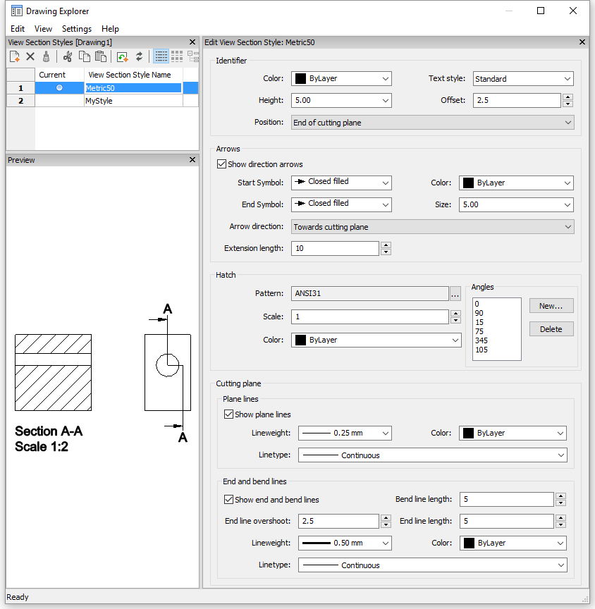
Displays the View Section Styles section of the Drawing Explorer dialog box:
Command Options
|
Option |
Description |
|
Creates a new view section style as a copy of the currently selected style. |
|
|
|
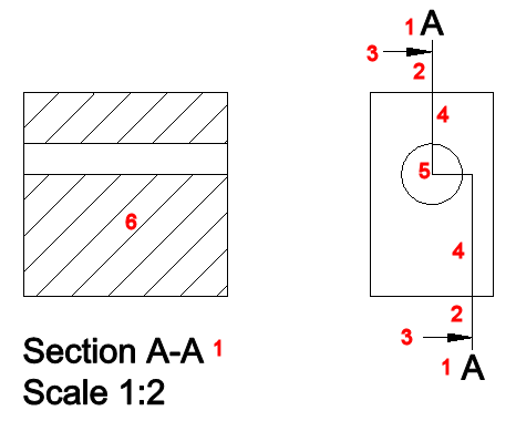
1. Identifier 2. Arrows 3. Allows extension length 4. Cutting plane lines 5. Cutting plane bend lines 6. Hatch
|
|
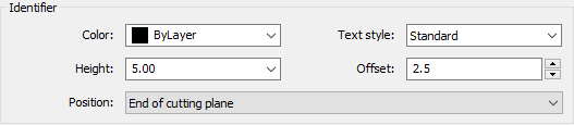
Sets the properties of the section identifier:
|
|
|
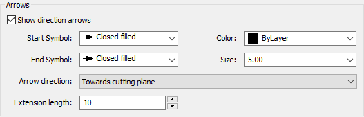
Sets the properties of the section arrows:
|
|
|
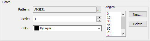
Sets the properties of the section hatching:
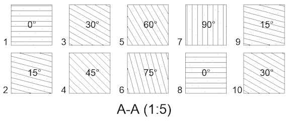
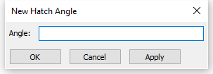
The first angle in the list is applied to the first solid in the model, the second angle to the second solid, the third angle to the third solid, etc. In the dialog above seven angles are defined, in a model containing 10 solids the hatch angles are applied as indicated in the section below. Because only 7 angles are defined, the first angle is applied to solid no. 8, the second angle to no. 9 etc. To add a new hatch angle, click the New... button. A dialog box displays:
To remove an angle, select the angle in the list, then click the Delete button. |
|
|
|
|
|
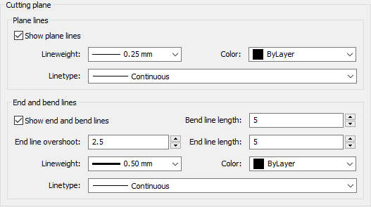
Sets the properties of the cutting plane indicator lines:
|
|
Related Commands
ViewBase - generates associative orthographic and standard isometric views of a 3D solid model in a paper space layout.
ViewDetail - creates a detail view of a portion of a standard generated drawing at a larger scale.
ViewDetailStyle - allows to specify the visual format of detail views and detail symbols.
ViewSection - creates a cross section view based on a standard drawing view generated by the ViewBase command in a paper space layout.
| © Menhirs NV. All rights reserved. |