![]() Pro, Platinum
Pro, Platinum![]() Pro, Platinum
Pro, Platinum![]() Pro, Platinum
Pro, Platinum
Creates a detail view of a portion of a standard generated drawing at a larger scale.
Accessing the Command
command bar: viewdetail
menu bar: View | Drawing Views | Detail View
toolbars:
Drawing Views | ![]()
Detail Section Types | ![]()
![]()
ribbon:
Annotate | Drawing Views| ![]()
![]()
Model | Drawing Views| ![]()
![]()
: viewdetail
Prompts you in the command bar:
Select drawing view: (Click inside a drawing view. Drawing view viewports highlight when you move the cursor inside their borders.)
Specify detail center or select boundary type [Circular/Rectangular] <Circular>: (Pick a point: this point is the center point of the detail view or choose an option.)
Select radius of detail view: (Pick a point or type a value to define the radius of the viewport of the detail view.)
Select position for detail view [Scale] <Cancel>: (Pick a point to position the detail view.)
Select option [Scale/Hidden lines/Tangent lines/anChor/Annotation/Boundary/modEl edge] <Cancel>: (Select an option or press Enter conclude.)
Command Options
|
Option |
Description |
|
Creates a circular boundary. (The Boundary option in the final prompt allows to switch the boundary to rectangular.) Prompts you: Select radius of detail view - Pick a point or type a value. |
|
|
Creates a rectangular boundary. (The Boundary option in the final prompt allows to switch the boundary to circular.) Prompts you: Select radius of detail view - Pick a point or type a value. |
|
|
By default the scale of the detail viewport is twice the parent viewport scale. Prompts you: Adjust view scale [Standard scales/Custom/Relative custom/Exit] <Standard scales>:
|
|
|
Allows to control the display of hidden lines. Prompts you: Show hidden lines [Yes/No/from Parent]:
|
|
|
Allows to control the display of tangent edges between a flat and a curved face (e.g. a filleted edge). Prompts you: Show tangent lines [Yes/No]:
|
|
|
Allows to control how to position the detail view inside the viewport in an update operation, when the extents (= bounding box) of the 3D geometry has been changed. Prompts you: Anchor view on paper space? [Yes/No]:
The AUTOVPFITTING system variable controls whether the size of the viewport is adjusted automatically to fit the current extents of the 3D geometry. By default AUTOVPFITTING = ON.
|
|
|
Controls the annotation of the detail view . Prompts you: Select annotation [Identifier/Label]:
|
|
|
Controls the boundary if the detail view : circular or rectangular. Prompts you: Detail boundary [Rectangular/Circular]: Choose an option.
|
|
|
Controls whether a connection line is drawn between the detail view and the detail boundary in the parent view. Prompts you: Model edge type [smooth with Border/smooth with Connection line]: Choose an option.
|
Grips Editing
Detail views can be edited through grips.
6 grips display:
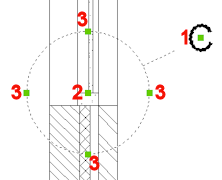
1. Controls the position of the identifier
2. Controls the position of the section detail.
3. 4 grips allow to control the size of the detail boundary.
Related Commands
ViewBase - generates associative orthographic and standard isometric views of a 3D solid model in a paper space layout.
ViewExport - exports the content of drawing views and sections obtained by VIEWBASE and VIEWSECTION to the Model Space of the drawing.
ViewDetailStyle - allows to specify the visual format of detail views and detail symbols.
ViewEdit - allows changing the scale and the hidden line visibility of drawing views.
ViewExport - Exports the content of drawing views obtained by VIEWBASE and VIEWSECTION to the Model Space of the drawing or to a new drawing.
ViewProj - generates additional projected views from an existing drawing view.
ViewSection - creates a cross section view based on a standard drawing view generated by the VIEWBASE command in a paper space layout.
ViewSectionStyle - allows to specify the visual format of section views and section lines.
ViewUpdate - updates a selection of drawing views or sections when VIEWUPDATEAUTO = 0.
| © Menhirs NV. All rights reserved. |