![]() Pro, Platinum
Pro, Platinum![]() Pro, Platinum
Pro, Platinum![]() Pro, Platinum
Pro, Platinum
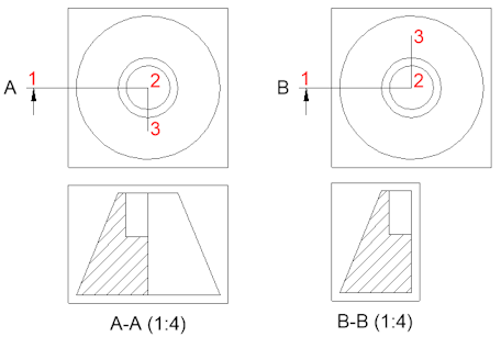
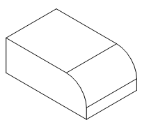
Creates a cross section view based on a standard drawing view generated by the ViewBase command in a paper space layout.
Accessing the Command
command bar: viewsection
menu bar: View| Drawing Views | Generate Section
toolbars:
View | Drawing Views | ![]()
Section types | ![]()
![]()
![]()
![]()
ribbon:
Annotate | Drawing Views| ![]()
![]()
Model | Drawing Views | ![]()
![]()
![]()
![]()
: bmgensection
Prompts you in the command bar:
Select drawing view: (Select a drawing view in the current paperspace layout.)
Specify start point of section line or select type [Full/Half/Offset/Aligned] <Full>: (Pick a point or select an option.)
Specify next point of section line [Done] <Done>: (Pick a point.)
The section view displays dynamically parallel to the section line. The view direction of the section view is defined by the position of the section view with respect to the section line.
Select position for section view: (Pick a point.)
Select option [Scale/Hidden lines/Tangent lines/anChor/Geometry/Annotation/Depth/Projection] <Cancel>: (Press <Enter> to finish or select an option.)
Command Options
|
Option |
Description |
|
Allows to control the shape of the section plane. Prompts you: Select type [Full/Half/Offset/Aligned] <Full>: Select an option.
|
|
|
Sets the Scale property of the paper space viewports for the various views. Prompts you: Adjust view scale [Standard scales/Custom/from Parent]: Select an option:
|
|
|
Allows to control the visibility of hidden lines. Prompts you in the command bar: Show hidden lines [Yes/No/from Parent]:
|
|
|
Allows to control the display of tangent edges between a flat and a curved face (e.g. a filleted edge). Prompts you: Show tangent lines [Yes/No]:
|
|
|
Allows to control how to position the view inside the viewport in an update operation, when the extents (= bounding box) of the 3D geometry has been changed. Prompts you: Anchor view on paper space? [Yes/No]:
The AUTOVPFITTING system variable controls whether the size of the viewport is adjusted automatically to fit the current extents of the 3D geometry. By default AUTOVPFITTING = ON. |
|
|
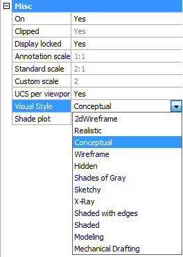
Defines the style for the isometric views: rendered 3D view or 2D drawing. Prompts you: Enable conceptual visual style for isometric views? [Yes/No] <No>:
|
|
|
Controls the annotation of the detail view or section view. Prompts you: Select annotation [Identifier/Label]:
|
|
|
Specifies the view depth of a section view. Prompts you: Choose depth mode [Full/Custom]:
|
|
|
The command prompts you: Select projection method [Normal/Orthogonal]: Select the desired method:
|
Grips Editing
Section lines can be edited through grips.
Select either the section line, one of the identifiers or an arrow.
5 Grips display:
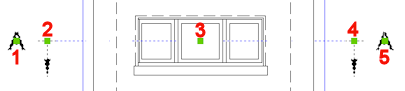
1. Controls the position of the first identifier.
2. Defines the start point of the section line.
3. Allows to move the section line.
4. Defines the endpoint of the section line.
5. Controls the position of the second identifier.
Related Commands
Flatshot - creates a hidden line representation of 3D solids in model space.
Solprof - creates a hidden line representation of 3D solids in a layout viewport.
MvSetup - Creates multiple paper space viewports; aligns, rotates and scales paper space viewports. In model space the command creates a rectangle, representing a paper sheet with respect to a specified scale.
ViewBase - generates associative orthographic and standard isometric views of a 3D solid model in a paper space layout.
ViewExport - exports the content of drawing views and sections obtained by VIEWBASE and VIEWSECTION to the Model Space of the drawing.
ViewDetail - creates a detail view of a portion of a standard generated drawing at a larger scale.
ViewDetailStyle - allows to specify the visual format of detail views and detail symbols.
ViewEdit - allows changing the scale and the hidden line visibility of drawing views.
ViewExport - Exports the content of drawing views obtained by VIEWBASE and VIEWSECTION to the Model Space of the drawing or to a new drawing.
ViewProj - generates additional projected views from an existing drawing view.
ViewSectionStyle - allows to specify the visual format of section views and section lines.
ViewUpdate - updates a selection of drawing views or sections when VIEWUPDATEAUTO = 0.
| © Menhirs NV. All rights reserved. |