![]() Generative Drafting improved in V14.2
Generative Drafting improved in V14.2![]()
Commands: VIEWBASE, VIEWSECTION, VIEWSECTIONSTYLE, VIEWPROJ, VIEWDETAIL, VIEWDETAILSTYLE, VIEWUPDATE, VIEWEXPORT and VIEWEDIT
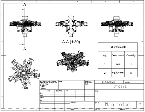
The Generated Drawing Views functionality allows to automatically generate associative orthographic and standard isometric views of a 3D solid model. All drawing views are placed in a paper space layout, they are not visible in model space.
Analytical hidden line removal (HLR) procedures are used to create the drawing views using standard 2D entities, mostly lines and arcs. Much like the result of the FlatShot command. Drawing views created in V14.1 will be automatically converted into HLR geometry by the ViewUpdate command.
The ViewBase command generates associative orthographic and standard isometric views of a 3D solid model in a paper space layout.
The ViewSection command creates a cross section view based on a standard drawing view generated by the ViewBase command in a paper space layout.
The ViewSectionStyle command allows to modify the appearance of the section views created by the ViewSection command.
The ViewProj command generates additional projected views from an existing generated drawing view.
The ViewDetail command creates a detail view of a portion of a standard generated drawing, at a larger scale.
The ViewdetailStyle command allows to modify the appearance of the detail views created by the ViewDetail command.
The ViewUpdate command Updates a selection of drawing views obtained by ViewBase and ViewSection when VIEWUPDATEAUTO = 0.
The ViewExport command exports the content of drawing views obtained by ViewBase and ViewSection to the Model Space of the drawing. This command can be used in paper space only.
The ViewEdit command allows changing the scale and the hidden line visibility of drawing views.
|
NOTE |
Drawing views generated in V14.2 or higher will show correctly in BricsCAD V13. The most recent V13.2 version is recommended. Drawing views generated in V14.2 or higher do not display in V12 and older BricsCAD versions. |
Tools to generate drawing views of your 3D solid model are available on:
The Generated Views toolbar, which is a flyout of the View toolbar:
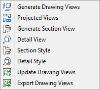
The View | Generated Views menu:
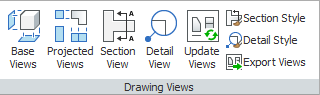
The Drawing Views panel of the Annotate Ribbon tab.
Standard views include multiview orthographic and isometric projections.
In a technical drawing, a multiview orthographic projection is an illustration technique in which up to six images of an object are generated, with each projection plane parallel to one of the coordinate axes of the object.
Isometric projection is a method represent three-dimensional objects in two dimensions in technical and engineering drawings. It is an axonometric projection in which the three coordinate axes appear equally foreshortened and the angles between any two of them are 120 degrees.
To generate the standard views of your 3D solid model, run the ViewBase command from model space.
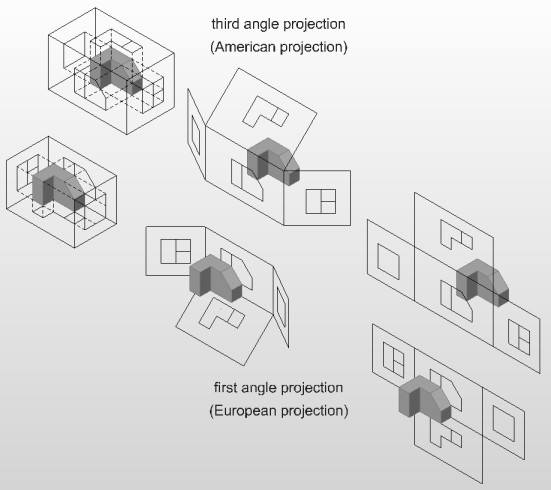
You can choose between first angle (European) projection or third angle (American) projection.
Orthographic projection (or orthogonal projection) is a means of representing a three-dimensional object in two dimensions. It is a parallel projection, where all the projection lines are orthogonal to the projection plane, resulting in every plane of the scene appearing in affine transformation on the viewing surface. It is further divided into multiview orthographic projections and axonometric projections.
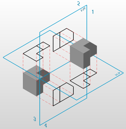
Two projection planes, one horizontal (H.P.) and one vertical (V.P.) divide the space in four quarters.
In the first angle projection system the model is placed in the first quarter space (first angle).
In the third angle projection system the model is placed in the third quarter (third angle).
With multiview orthographic projections, up to six pictures of a 3D model are produced, with each projection plane parallel to one of the coordinate axes of the model. The views are positioned relative to each other according to either of two schemes: first-angle or third-angle projection. In each, the appearances of views may be thought of as being projected onto planes that form a 6-sided box around the model.
The projection type is set by the Projection Type option of the ViewBase command or by editing the PROJECTIONTYPE system variable:
0 = First angle projection
1 = Third angle projection
The value of the PROJECTIONTYPE system variable is saved in the drawing.
Generated drawing view lines are created on default layers:
BM_Isometric_Hidden
BM_Isometric_Visible
BM_Ortho_Hidden
BM_Ortho_Visible
The display of the BM_Isometric_Hidden layer is turned off by default.
Additional projected views can be added using the ViewProj command. A projected view inherits the scale, display settings and alignment from the parent view.
Generating Cross Section Views
A cross section is the intersection of a 3D solid model with a section plane. In technical drawings, the internal parts of the 3D model are hatched in cross sections.
To generate section views of a 3D solid model, run the ViewSection command from the paper space layout where the standard drawing views exist.
By default BricsCAD checks whether the source 3D solid model was modified and automatically recalculates the drawing when:
opening a paper space layout containing out-of-date views if the VIEWUPDATEAUTO system variable is ON.
running the ViewUpdate command.
running the BmUpdate command (BricsCAD Platinum only).
|
NOTE |
Hidden line removal calculation might take some time for complex 3D models. In such cases it is recommended to set VIEWUPDATEAUTO = OFF. The viewport border of out-of-date drawing views turns red to indicate an update is needed. When executing the ViewUpdate command, BricsCAD prompts you to either select the drawing views to be updated or update all drawing views. |
Exporting Views to Model Space
The associativity mechanism of drawing views in a paper space layout allow limited control by the user. Such views can be moved or scaled, but you cannot edit the geometry. In order to get the full control to the drawing views geometry the ViewExport command allows to move or copy drawing views to model space or to a separate drawing. Exported drawing views loose their associativity with the 3D model and become standard blocks, which can be exploded, edited, erased, etc&ldots;
The first time the ViewBase command is launched, four new layers are created: two for basic orthographic views:
BM_Ortho_Hidden: hidden lines in orthographic drawing views
BM_Ortho_Visible: visible lines in orthographic drawing views
BM_Isometric_Hidden: hidden lines in isometric drawing views
BM_Isometric_Visible: visible lines in isometric drawing views
By default the display of the BM_Isometric_Hidden layer is switched off. Switch the layer on to have hidden lines in isometric views.
Edit the properties of these layers, such as linetype, lineweight or color, to modify the display of the drawing views.
| © Menhirs NV. All rights reserved. |