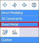
![]() Working with Sheet Metal Parts
Working with Sheet Metal Parts![]()
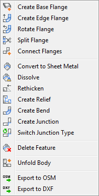
Commands: SmFlangeBase, SmFlangeEdge, SmFlangeRotate, SmFlangeConnect and SmUnfold
Sheet metal design allows you to model sheet metal parts and generate their unfolded representations with manufacturing information.
You can create complex sheet metal parts with BricsCAD easily and rapidly, because the design process is different from manufacturing process. Do not think in terms of a planar sheet that should be cut and bent, but model your part directly as you create solid bodies with Direct Modeling tools.
Creating a sheet metal part in BricsCAD consists of the following basic steps:
Form features are smart regions (groups of faces) of your 3D part. Each feature maintains specific spatial and parametric relationship between its faces and some adjacent faces. Form features allow you to embed design intent into your model. You do not create features by hand, they are created automatically depending on a particular geometric operation you apply.
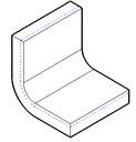
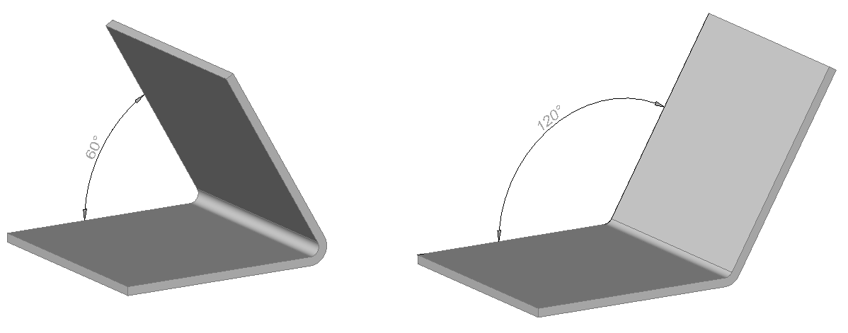
Main feature of any sheet metal part is a flange, which consists of two parallel planar faces. This distance between them is equal to the material thickness. When you modify the model, this distance relation is always maintained automatically. Other faces, which are adjacent to flange faces and do not belong to bends are called thickness faces. They are always perpendicular to flange faces.
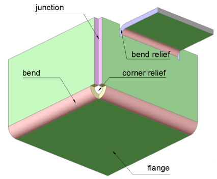
Two flanges are connected by a bend. A bend consists of two coaxial cylindrical faces, which are always tangent to the adjacent planar faces of the flanges.
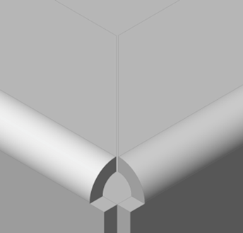
Group of faces representing a technological cut between two flanges of different width connected with a bend. The bend relief feature maintains the distance between two opposite faces of the cut.
Group of faces representing a cut in the corner where three flanges meet together. Corner relief feature maintains the form and size of this cut.
Junction feature consists of two thickness faces of adjacent flanges, which are not connected via bend.
The material deformation properties for bending is based on the assumption that there is internal surface for the sheet metal part which is not deformed when the sheet is bent. From the variety of internal surfaces the one is selected, which is equidistant from one side of the bend. The surface is local for each bend, and for simple cases it can be propagated on entire part, like the one on the picture. We assume that this surface is not stretched stretch during bending.
|
|
|
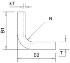
T: thickness of the sheet metal part
R: internal radius of the bend
The K-factor (k) is the ratio of the location of the neutral surface to the material thickness. As a result the neutral surface lies at a distance kT from the internal surface of the bend. The bend radius of the neutral surface equals R + kT. The K-Factor is a simple geometric calculation of the location of the neutral surface. Forming stresses and other unknown (error) factors are not taken into account. The K-Factor depends on many factors, including the kind of material, bending type, tools, etc ... The K-Factor typically lies between 0.3 and 0.5. The default K-Factor for a bend radius equal to the material thickness (T) is 0.27324.
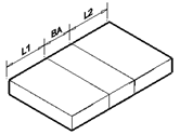
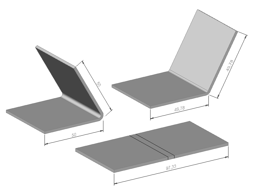
In the unfolded state of a sheet metal part, the flanges (L1 and L2) are not stretched. The bent part is indicated as BA: bend allowance. The BA equals the length of the unfolded neutral surface:
BA = BendAngle * (R + kT)
In real world practice it is hard to measure the K-Factor or the bend allowance. The following formula allows to calculate the tangential Bend Deduction (BD):
BD = B1 + B2 - Unfolded Length = B1 + B2 - (L1 + L2 + BA)
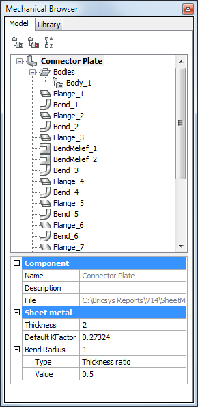
For simple cases the K-Factor value can be overridden in the browser, for maximal precision a bend table containing tangential bend deductions has to be provided. For each sheet metal part, you can either specify a K-factor or use the default one.
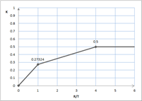
To change the K-Factor for a sheet metal part, select the root node in the Mechanical Browser and type a value in the K-Factor field. The value must lie in the range [0, 1], since the neutral surface is located inside the sheet metal part. In BricsCAD the K-Factor is defined for bend radius equal to the material thickness (R/T = 1); to compute the value of K-Factor for an arbitrary bend radius, BricsCAD uses a special interpolation technique which is proved to be valid for industrial sheet metal applications. The image below shows the interpolation strategy: for R/T < 1 the linear interpolation is done between 0 and 0.27324, for 1 < R/T < 4 the K-Factor is linearly interpolated between 0.27324 and 0.5 and if R/T is greater than 4, the K-Factor is constant and equals 0.5 . Physically it means that if the bend radius is much larger than the thickness (at least 4 times), the material stretch is can be neglected.
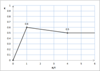
The K-Factor parameter one can control in the browser is for R/T. I.e. if we set the value to 0.6, the interpolation law leads to the following result:
T = 2, R = 2, B1 = 100, B2 = 100
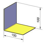
Setting K=0 gives L1=L2=96, Unfolded Length = 96, thus BA is 3.14.
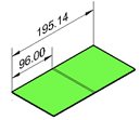
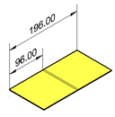
This value fits the formula exactly: a straight angle in radians roughly equals 1.57 (PI/2). The default K-Factor 0.27324 gives an Unfolded Length = 196.
Or: L1=L2=96 (flanges are not deformed), the BA = 4 as we can compute from the dimensions (196 - 2*96) or from the Bend Allowance formula: BA = BendAngle * (R + kT) = 1.57 * (2 + 2*0.27324) = 4
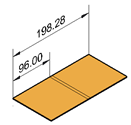
Finally, maximizing K-Factor results in an Unfolded Length = 198.28. This is the maximal value one can achieve in this example, since the neutral surface is taken from external side of the bend.
The Bend Deduction (BD) for k = 0.27324:
BD = B1 + B2 - Unfolded Length = 100 + 100 - 196 = 4
Bend tables are a more reliable way to express material deformation properties. When you bend a flat sheet of a particular material, you can measure its length before and after this process. You repeat this procedure for different bend angles, bend radius, and sheet thickness and save the measurements in a bend table. Then these measurements can be taken into account to compute the correct unfolded length for all parts made of the same material.
In a bend table, you can add the results for as many different bend angles as you want. However, in most cases it suffices to measure the length for a 90 degrees angle. BricsCAD will automatically compute the length for other bend angles using a reliable interpolation technique.
Bend tables are stored in a *.csv (comma separated values) file format. You can create such a table in an ASCII text editor, such as Notepad, but a more reliable and easier way is to create a table in a spreadsheet, such as Microsoft Excel or LibreOffice and then export it to .csv file format.
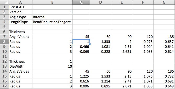
Bend tables in BricsCAD have the following structure:
The following rules apply:
The content of the first cell reads "BricsCAD”.
Version: currently supported version is 1.
AngleType:
Currently only internal bend angles are supported:
LengthType: the
semantics of the value in the cells of the bend table
corresponding to a particular bend angle and bend radius. Now only
bend deduction measured from the tangent point is supported
(”BendDeductionTangent”). Bend deduction (BD) is the difference
between the sum of the lengths of two flanges measured to the
tangent point on a 3D model and the length of the same fragment in
the unfolded state:
Within the defined header, several tables can exist. For each table, the first key is the of the sheet metal part, the second key, DieWidth, is optional. The Thickness / DieWidth pairs must be unique. If the DieWidth is not defined, only one unique Thickness value key is allowed, but multiple thickness values can be added. When a bend table is used to control the unfolding process, the Thickness and DieWidth, defined in the sheet metal part, must exist in the bend table. If the table is not found the default K-Factor policy is used.
Once the bend table is found in the .csv, it
will be used to unfold the sheet metal part. Using the sample bend
table above, let’s have a look a few cases:
T = Thickness, R = Internal Bend Radius,
A = Bend Angle
1. T = 1, R = 2, A = 45. Then after unfolding it will obtain the BD = 0.466, because both R and A are found in the bend table for the given thickness.
2. T = 1, R = 2.5, A = 45. A = 45 is found, but R = 2.5 is missing: the interpolation of BD between R=2 and R=3 is used.
3. T = 1, R = 2.5,
A = 75. Neither R nor A is found in the table: the following cells
are used to calculate the value of BD: (R=2, A=60), (R=3, A=60),
(R=2, A=90) and (R=3, A=90).
The top-of-the-edge algorithm is used to calculate the
interpolation. For example, linear interpolation on adjacent BD
values render unnatural results, which will not match the real
bending results. Also keep in mind that for a given T, R and A not
all BD values make sense: a random one might place the neutral
surface outside the sheet metal part, or expressed in K-Factor
(which can be deduced from BD), the K-Factor can be out of range
[0, 1]. In this case, the BD for the default K-Factor will be
used.
If you produce your sheet metal parts with
different tools, you can describe them in one bend table using
DieWidth parameter.
A sample bend table is provided for your convenience in the
..\Samples\Mechanical\bend_tables
subfolder of the BricsCAD program folder (e.g. C:\Program Files\Bricsys\BricsCAD V14
en_US\Samples\Mechanical\bend_tables). Please notice that
writing rights to this folder might be limited. In such case you
need to copy the bend tables to a different folder in which you
have full access rights.
To set the bend table for your sheet metal part:
To update the bend table set previously:
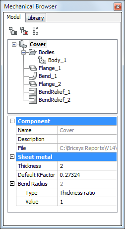
The Mechanical Browser for Sheet Metal
All features of a sheet metal part are listed in the Mechanical Browser.
When you select a feature in the Mechanical Browser, its faces are highlighted in the model area.
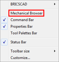
The Mechanical Browser automatically opens when switching to the 3D Modeling or Mechanical workspace.
To open the Mechanical Browser manually do the following:
|
NOTE |
When you right click a feature in the browser, then select Dissolve from the context menu. the selected feature is removed from the part, but it will keep its geometry. However, design intent (spatial and parametric relationships between the feature’s faces) associated with the geometry of a dissolved feature is removed. |
|
Icon |
Command |
Description |
|
|
Creates a base flange. |
|
|
|
Creates an edge flange. |
|
|
|
Rotates a flange. |
|
|
|
Splits a flange along a line drawn on its face. |
|
|
|
Closes gaps between two arbitrarily oriented flanges. |
|
|
|
Automatically recognizes flanges and bends in a 3D solid. |
|
|
|
Removes sheet metal data from the selected faces. |
|
|
|
Restores the 3D solid model of a sheet metal part by thickening one of its sides (all thickness faces become perpendicular to flange faces). |
|
|
|
Makes proper corner and bend reliefs. Corner reliefs are built on corners which have three or more adjacent flanges. Bend reliefs are built on the start and end of a flange edge . |
|
|
|
Converts hard edges (sharp edges between flange faces) into bends. |
|
|
|
Converts hard edges into junctions. |
|
|
|
Allows changing a symmetrical junction feature to one with overlapping faces. |
|
|
|
Removes a junction by restoring a hard edge between two flanges; removes a flange with all the bends adjacent to it. The adjacent flanges are extended up to a junction configuration with the flange being deleted. |
|
|
|
Unfolds the sheet metal body. |
|
|
|
Exports a sheet metal solid to the .osm (Open Sheet Metal) file format. |
|
|
|
Exports the unfolded representation of a sheet metal body as a 2D profile in .dxf / .dwg file format. |
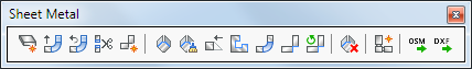
The Sheet Metal tools are available:

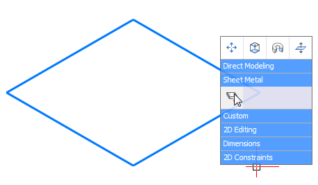
Start to design your sheet metal part with creating its base flange. To create a base flange, select a closed planar profile and call SmFlangeBase command.
Do one of the following:
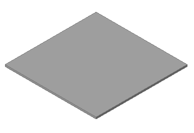
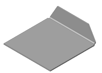
A base flange is a body created by extruding the selected profile to a height equal to the default value of the Thickness property of the sheet metal part
To change the thickness of your sheet metal part, type the appropriate value in the Thickness field in the Mechanical Browser.
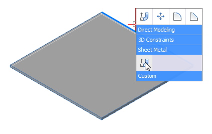
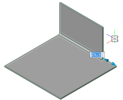
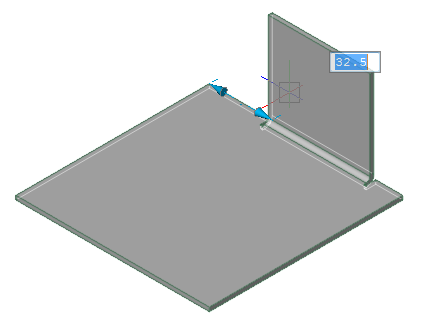
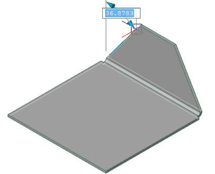
You can add an additional flange to your sheet metal part by pulling a linear edge of an existing flange. Select an edge and select the SmEdgeFlange command in the Sheet Metal section of the Quad cursor menu.
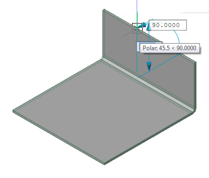
Move your mouse pointer to define the desired length of the edge flange and the angle between two flanges. You can also use the corresponding dynamic dimensions to type the desired values.
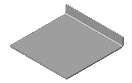
To create an edge flange of which the width is different from the width of the edge, select the Width option of SmEdgeFlange command and define offsets from both sides of the edge.
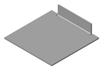
Note that when you create an edge flange of different width, the corresponding bend reliefs are created automatically.
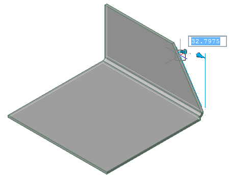
Create Edge Flange With Taper Angle(s)
You can create trapezoidal edge flanges using Taper angle option of SmEdgeFlange command:
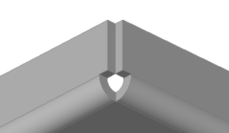
When you pull an edge of a flange that is adjacent to a bend edge to create a new flange with SmFlangeEdge command, a corner relief is created automatically in the corner where three flanges meet together:
This operation also creates a junction between two flanges, which are not connected with a bend.
You can rotate a flange with DmRotate
command (![]() ) , however, you will usually
obtain a better result with SmFlangeRotate
(
) , however, you will usually
obtain a better result with SmFlangeRotate
(![]() ). This command automatically
selects the rotation axis to respect the design intent of your
sheet metal part.
). This command automatically
selects the rotation axis to respect the design intent of your
sheet metal part.
The command bar reads: Select a flange face to rotate:
Flange faces highlight under the cursor.
|
NOTE |
If you apply DmRotate command to a flange, which is connected with other flanges via junction features, these features are automatically dissolved before the rotation. |
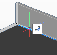
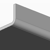
The SmFlangeConnect command closes gaps between two arbitrarily oriented flanges.
The command bar reads: Select planar thickness faces of two flanges:
Flange faces highlight under the cursor.
To convert geometry to a valid sheet metal part
You can create a sheet metal part from any existing 3D solid geometry, created in BricsCAD or imported from another CAD system. However, the geometry might be incorrect as a sheet metal model, such as missing bends and reliefs or thickness faces which are not orthogonal to the flange faces. BricsCAD contains a dedicated toolset to convert such geometry to a valid sheet metal part and add all missing sheet metal features to it.
To convert geometry to a sheet metal part, select one or more 3D solids and call the SmConvert command.
After conversion, main sheet metal features (flanges and bends) are recognized in the selected geometry and will be listed in the Mechanical Browser.
Converted bodies can be unfolded or exported to .dxf or .osm file formats for processing by a CAM system. In some cases converted bodies should be fixed before unfolding/exporting.
This includes:
Creation of missing reliefs: SmReliefCreate command.
Converting hard edges to bends or junctions: SmJunctionCreate command.
Splitting flanges: SmFlangeSplit command.
Re-thickening sheet metal bodies: SmRethicken command.
The command bar reads: Select a hard edge or bend face, flange face, 3D solid / <Entire model>:
The relief is created.
|
|
|
|
Selected bend faces |
Created reliefs |
|
NOTE |
The selected items can be a 3D solid with sheet metal features, a face or a hard edge of the solid. To create a relief locally, you can select one or two hard edges, one or two bends or a bend and a hard edge. If a 3D solid is selected the command recognizes the places where corner or bend reliefs are needed and creates them automatically. If two hard edges or two bends or a bend and a hard edge at a corner are selected, the command tries to create a corner relief. |
Converting hard edges to bends or junctions
If adjacent flanges of a sheet metal part are not connected by a bend or junction, the part cannot be unfolded or exported to a CAM system. To fix this, each hard edge between adjacent flanges must be converted to a bend or a junction.
The command bar reads: Select flange faces or hard edges:
|
|
|
|
Selected hard edge |
Created bend |
The command bar reads: Select flange faces or hard edges:
|
|
|
|
Selected hard edges |
Created junctions |
In some cases a flange is better split to minimize the material consumption, e.g. when a flange has a large hole like on the image below:
The command bar reads: Select a flange face:
To re-thicken a sheet metal body
If a sheet metal body has thickness faces, which are not perpendicular to the flange/bend faces, such a part cannot be correctly manufactured from a sheet of metal using traditional tools.
The command bar reads: Select a face to rethicken:
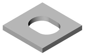
Here is the same model before
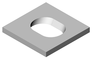
and after re-thickening:
To change the thickness of a sheet metal part:
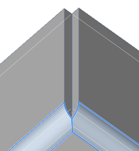
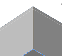
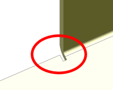
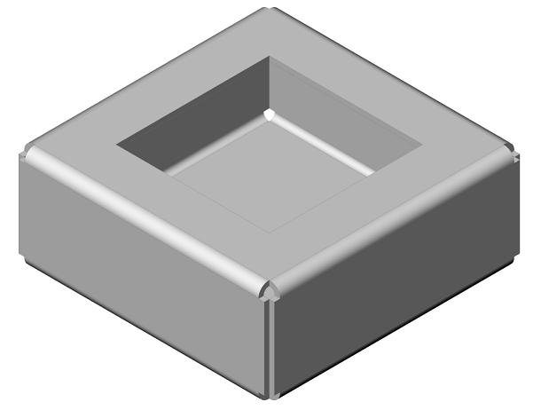
By default, BricsCAD creates symmetric junctions, as shown in the image below:
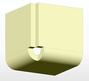
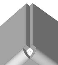
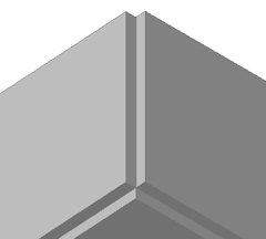
The SmJunctionSwitch command allows changing a symmetrical junction feature to one with overlapping faces.
hover the cursor over one the thickness faces of this junction,
Select Switch Junction
Type in the Sheet Metal command group in the Quad.
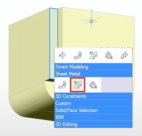
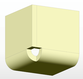
The selected thickness face is aligned with the flange face.
Method 1:
Select the corresponding junction in the tree.
The junction properties display in the bottom part of the
Mechanical Browser.
Select the Connection type property.
Choose the desired junction type.
The options are: Symmetric,
Aligned to Flange_X or Aligned to Flange_Y.
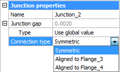
The junction is updated accordingly.
Method 2:
Select the corresponding junction in the tree.
A context menu displays:
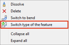
Right click and choose Switch type of feature in the context menu.
|
NOTE |
Both symmetric and aligned junctions maintain the same gap value between connected flanges. |
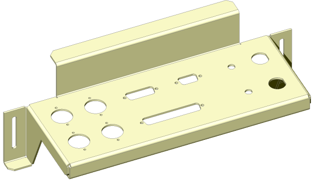
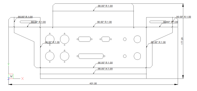
To unfold your sheet metal body, select a start flange face and run SmUnfold command. BricsCAD will automatically create a solid body corresponding to a flat sheet of metal needed to manufacture your sheet metal part using bending techniques. This sheet is placed on XY-plane and is oriented along the coordinate axes similarly to the orientation of the initial body in 3D space. To change the orientation of the unfolding in OZ axis, run SmUnfold command again and select the opposite face of the initial body.
The SmUnfold command prompts you to either:
Keep the 3D solid in the model.
Save the 3D solid in a separate drawing file.
Convert the solid to a 2D drawing file (*.dwg or *.dxf)
Overall dimension and bending annotations for manufacturing are added to the exported drawing automatically.
The SmUnfold command takes the deformation of the sheet metal material during bending into account. When a flat sheet of metal is bent into a 3D part with a bending tool (like a press break), the material is plastically deformed, it is compressed inside the bend and stretched outside of it. So the length of the part measured along its surface is different in flat and bend states. BricsCAD is able to automatically compute the proper unfolded length of your part based on the material deformation properties. These properties can be defined by setting the value of K-Factor parameter or by attaching a bend table.
Sheet metal parts created or edited in BricsCAD can be then processed by different CAM systems (such as JETCAM or CADMAN-B) to generate NC code for cutting and bending machines.
The SmExport2d command exports the unfolded representation of a sheet metal body as a 2D profile in .dxf / .dwg file format.
The SmExportOSM command exports a sheet metal solid to the .osm (Open Sheet Metal) file format (native for CADMAN-B CAM system).
| © Menhirs NV. All rights reserved. |