![]() Pro, Platinum
Pro, Platinum![]() Pro, Platinum
Pro, Platinum![]() Pro, Platinum
Pro, Platinum
Creates 3D solids passing through two or more cross sections.
Accessing the Command
command bar: loft
menu bar: Model | 3D Solids | Loft
toolbar: 3D Modeling | ![]()
: loft
Prompts you in the command bar:
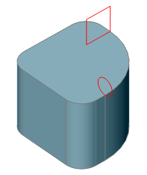
Select cross sections in lofting order [MOde]: (Select a closed 2D entity or a planar face of a 3D solid; or choose the Mode option.)
Select cross sections in lofting order [MOde]: (Select a closed 2D entity or a planar face of a 3D solid; or choose the Mode option.)
The first part of the lofted 3D solid is created.
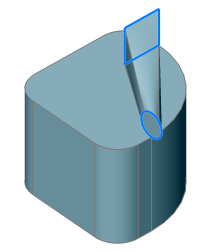
Select cross sections in lofting order [MOde]: (Select more 2D entities or planar faces; or choose the Mode option; or press Enter to stop selecting cross sections.)
The the lofted 3D solid is created.
3 cross sections selected
Enter an option [Guides/Cross sections only/Settings] <Cross sections only>: (Press Enter or choose an option.)
|
|
|
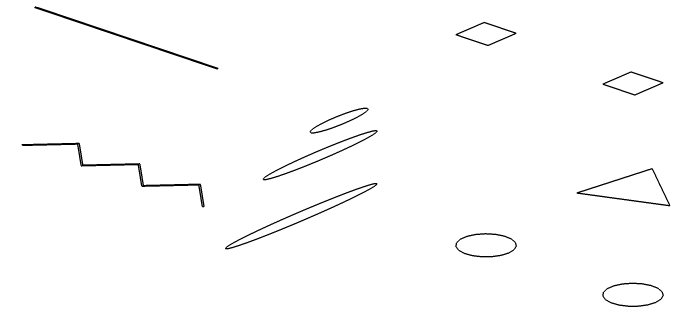
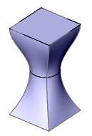
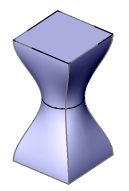
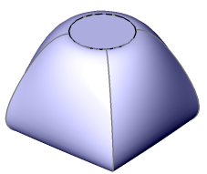
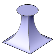
Cross sections |
|
|
|
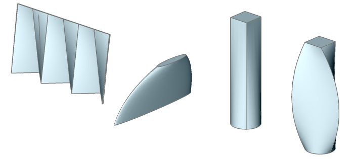
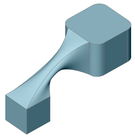
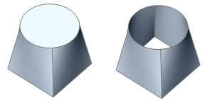
Lofted solids. |
|
|
|
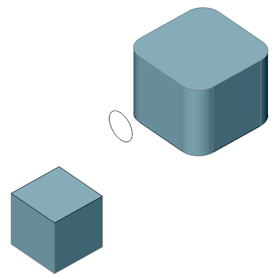
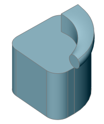
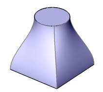
Lofted solid using faces of 3D solids and a circle. |
Command Options
|
Option |
Description |
||
|
Allows to create a solid (left) or a surface (right).
Prompts you: Choose type of created entity [SOlid/SUrface] <SOlid>:
|
|||
|
Uses the selected cross sections only, no guides. If DELOBJ = 1 or 2, the selected 2D entities are deleted. |
|||
|
Use guide lines between the selected cross sections. If DELOBJ = 2, the selected guide entities are deleted. Prompts you: Select guide curves: Select a linear entity (lines, arcs, elliptical arcs, splines, single-segment 2D polylines and edges of 3D solids are accepted.) Select guide curves: Select more linear entities or press Enter.
|
|||
|
|
|
|
|
|
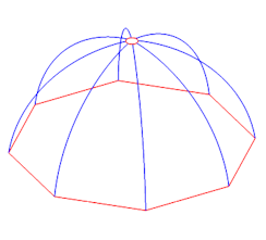
Cross sections (red) and guides (blues) |
Cross sections only |
All guides selected |
|
|
|
|
|
|
|
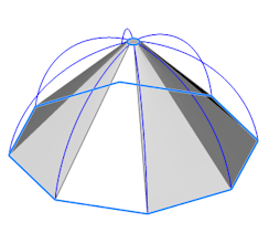
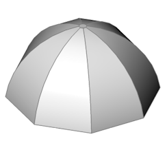
Cross sections (red). |
Cross sections selected only |
Curved solid edge selected as a guide. |
|
|
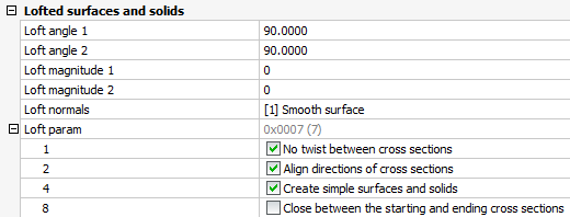
Allows to set the Loft surfaces and solids settings. The default settings are controlled through a series of system variables, which are saved in the drawing:
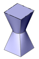
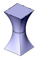
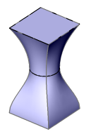
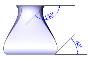
Loft Normals settings:
Prompts you: Current option is Smooth. Enter an option [Ruled/Smooth fit/Normal to/Draft angles] <eXit>:
Solid surface is normal to the start (left), end (middle), both (right) cross sections
Loft Angles = 90° (left), Loft Angles = 0° (middle), Loft Angles = 180° (right)
|
|||
Related Commands
Extrude - extrudes 2D entities to 3D solids.
dmExtrude - creates a 3D solids by extruding closed 2D entities or regions.
dmRevolve - creates 3D solids by revolution of closed 2D entities or regions about an axis.
dmTwist - modifies a 3D solid, surface or region by twisting a portion defined by two points around an axis.
Revolve - revolves 2D closed entities to turn them into 3D solids.
RevSurf - creates a 3D mesh surface by revolving a linear entity around a line.
Sweep - creates a 3D solid by sweeping a closed 2D entity along a path.
| © Menhirs NV. All rights reserved. |