Commands: 2DINTERSECTION, 3DINTERSECTION, NEAREST, CENTER, ENDPOINT, EXTENSION, FROM, GCENTER, INSERTION, INTERSECTION, MIDPOINT, MTP, NONE, PARALLEL, PERPENDICULAR, POINT, QUADRANT, TANGENT
Entity snaps enable you to quickly select exact geometric points on existing entities without having to know the exact coordinates of those points. With entity snaps, you can select the end point of a line or arc, the center point of a circle, the intersection of any two entities, or any other geometrically significant position. You can also use entity snaps to draw entities that are tangent or perpendicular to an existing entity. You can use entity snaps any time you need to specify a point.
You can work with entity snaps in one of two ways
Enable a running entity snap that remains in effect until you turn it off by choosing an entity snap when no other command is active.
Enable a one-time entity snap for a single selection by choosing an entity snap when another command is active. You can also use a one-time entity snap to override a running entity snap.
When using entity snaps, the program recognizes only visible entities or visible portions of entities. You cannot snap to entities on layers that have been turned off or to the blank portions of dashed lines.
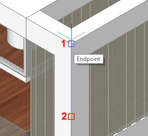
If the APBOX system variable is on, the entity Snap Aperture Box is added to the crosshairs when one or more entity snaps are active.
When you move the cross hairs, the program snaps to the snap point closest to the center of the Snap Aperture Box. The Snap Marker indicates the current snap point.
The DRAGSNAP system variable controls the snap behavior while 'dragging', providing an increased WYSIWIG experience. DRAGSNAP controls whether rubberband dynamics are displayed at the current cursor location or at the current entity snap location. DRAGSNAP applies to all modify commands that display dynamics, such as COPY, PASTECLIP, PASTEBLOCK, MOVE, ROTATE, MIRROR, SCALE and STRETCH.
DRAGSNAP = 0 (Default),:dragged entities display at the cursor location.
DRAGSNAP = 1: dragged entities display at the current entity snap location.
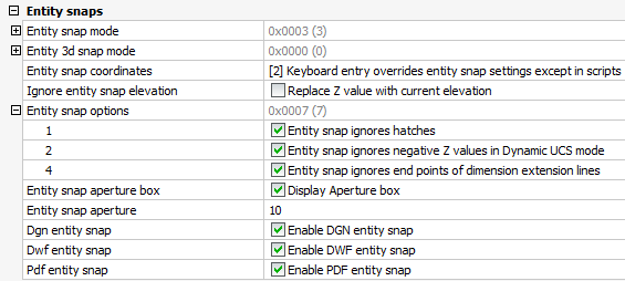
The OSOPTIONS system variable suppresses entity snaps on certain entity types. The value is stored as a bitcode using the sum of the values of the selected options.
1: Entity snapping is disabled for hatch entities.
2: Entity snapping is disabled for geometry with negative Z values when using a dynamic UCS.
4: Entity snapping is disabled for endpoints of dimension extension lines.
|
NOTE |
Press the TAB key, without moving the mouse, to cycle through all possible entity snaps. If the DYNMODE variable has a positive value (Dynamic Dimensions switched ON) entity snap cycling is not possible. Click the DYNMODE field in the Status Bar to toggle the display of dynamic dimensions. |
To define the Entity Snap settings
Open the Settings dialog.
In the Settings dialog, expand the Program Options settings class.
Under Program Options expand the Display settings group, then scroll down to the Entity Snap settings.
|
User Preference |
Title |
Description |
|
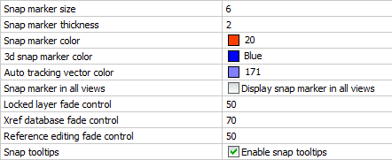
SnapMarkerSize |
Snap marker size |
Sets the size of the snap marker. (default size is 6) |
|
SnapMarkerThickness |
Snap marker thickness |
Sets the thickness of the snap marker. (default thickness is 2) |
|
SnapMarkerColor |
Snap marker color |
Sets the color of the snap marker. (default color = 20) |
|
3dSnapMarkerColor |
3d snap marker color |
Sets the color of the 3d snap marker (default color = 5 (Blue)). The 3d snap marker (1) displays the identified 3d point, the snap marker (2) displays at the current Elevation height. The 3d snap marker displays only if OSNAPZ = 1 (
|
|
|
|
|
|
DisplaySnapMarkerInAllViews |
Snap marker in all views |
If multiple viewports are open, enables the display of the snap marker in all viewports. |
|
DisplayTooltips |
Snap tooltips |
Enables the display of the Entity Snap tooltips. |
Under Drawing expand the Drafting settings group then go to Coordinate Input > Entity Snaps.
|
System Variable |
Title |
Description |
|
OSMODE |
Entity snap mode |
Sets the entity snap modes and toggles entity snap on/off. |
|
3DOSMODE |
3D entity snap mode |
Sets the entity snap modes for 3D entity features such as the midpoint of an edge or the center of a face. |
|
OSNAPCOORD |
Entity snap coordinates |
Determines whether entity snaps override keyboard coordinate entry. |
|
OSNAPZ |
Ignore entity snap elevation |
Replaces the Z-coordinate of the snapping point with the current value of the ELEVATION system variable. |
|
OSOPTIONS |
Entity snap options |
Suppresses entity snaps on hatches and/or dimension extension lines or negative z-values in dynamic UCS mode. |
|
APBOX |
Entity snap aperture box |
Toggles the display of the aperture box (2). |
|
APERTURE |
Entity snap aperture |
Sets the size of the Autosnap aperture box. (default size is 10). |
|
DGNOSNAP |
DGN entity snap |
Enables entity snapping to entities in DGN underlay files. |
|
DWFOSNAP |
DWF entity snap |
Enables entity snapping to entities in DWF underlay files. |
|
PDFOSNAP |
PDF entity snap |
Enables snapping to the geometry in PDF underlay files. |
Do one of the following:
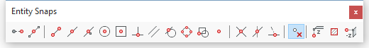
When no command is active, the above procedures toggle the Entity Snap modes on/off.
When a command is active, the above procedures set a 'one shot' override of the current Entity Snap modes.
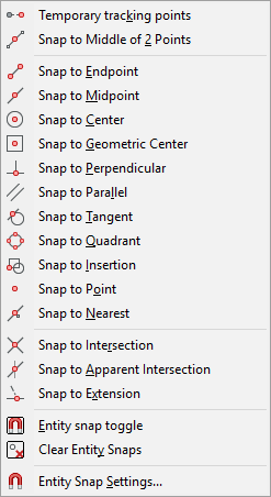
Alternatively you can type a single letter shortcut as indicated in the table below.
|
Name |
Icon |
Marker |
Context |
Transparent shortcut** |
Description |
|
TK |
|
|
|
tk |
Use temporary tracking points. Prompts you to identify temporary points; press Enter to accept the last temporary point. |
|
|
|
2 |
mtp |
Snaps to a point in the middle between two points. Prompts you to identify two points. |
|
|
|
|
|
|
|
|
|
|
|
E |
end |
Snaps to the nearest endpoint of an entity or polyline segment. |
|
|
|
|
M |
mid |
Snaps to the midpoint of an entity or polyline segment. |
|
|
|
|
N |
nea |
Snaps to the nearest point on an entity. |
|
|
|
|
C |
cen |
Snaps to the center point of an arc, circle, polygon, ellipse or elliptical arc. Snaps to the center of gravity of a closed polyline. |
|
|
|
|
G |
gce |
Snaps to the centroid of any closed polylines and splines, planar 3d polylines, regions and planar faces of 3D solids. |
|
|
|
|
P |
per |
Snaps to the perpendicular point of another entity. You can snap to an arc, circle, ellipse, line, polyline, infinite line, ray, spline or edge of a plane to form a perpendicular alignment with that entity or with an extension of that entity. |
|
|
|
|
L |
par |
Displays a tracking line parallel to the selected entity. |
|
|
|
|
T |
tan |
Snaps to the point on an arc, ellipse, spline or circle that, when connected to the previous point, forms a line tangent to that entity. |
|
|
|
|
Q |
qua |
Snaps to the closest quadrant of an arc, circle, ellipse, or elliptical arc. |
|
|
|
|
I |
ins |
Snaps to the insertion point of an attribute, block or text entity. |
|
|
|
|
O |
poi nod |
Snaps to a point entity. |
|
|
|
|
R |
int |
Snaps to the intersection of any combination of entities. |
|
|
|
|
A |
app |
Snaps to the apparent intersection in the current view of two entities that do not intersect in three-dimensional space. |
|
|
|
|
X |
ext |
Snaps to the extension of an entity or to the intersection of the extension of two entities. |
|
|
|
|
Y |
non |
Turns off all entity snap modes. |
* Type this letter to quickly select the entity snap mode in the right click context menu.
** Type the transparent shortcut in the command bar when a command prompts for a point. Other running entity snaps are temporarily disabled.
|
System Variable |
Icon |
Description |
|
OSNAPZ |
|
Ignore entity snap elevation: replaces the Z coordinate of the snapped point with the current value of the ELEVATION system variable. |
|
OSOPTIONS |
|
Entity snap to hatches: allows to snap to hatches. |
|
OSOPTIONS |
|
Entity snap to negative-z: allows entity snaps with a negative z-value when a Dynamic UCS is active, |
|
NOTE |
You can toggle the Entity Snaps on/off:
|
Working with multiple Entity Snap modes
|
NOTES |
|
To snap to the extension of two entities
|
NOTE |
You can snap to the extension of lines, polylines, arcs and elliptical arcs |
Using temporary tracking points
When using temporary tracking points, Polar Tracking must be on and it is recommended to have dynamic dimensions active as well.
The command is suspended temporarily.
You are prompted: Specify first temporary tracking point:
The command resumes.
Using 'Middle of 2 points' snap
You are prompted: First point of mid:
Using the Parallel entity snap
| © Menhirs NV. All rights reserved. |