Click the Form Feature tool button
(![]() ) on the Sheet Metal toolbar.
) on the Sheet Metal toolbar.
Click the Form Feature tool button
( ![]() ) on the Sheet Metal ribbon bar.
) on the Sheet Metal ribbon bar.
Choose Insert Form Feature in theSheet Metal menu.
Type bminsert in the command bar, then press Enter.
Commands: SMFORM, SMCONVERT, SMREPLACE, BMINSERT
Form features a kind of sheet metal features, corresponding to the result of application of a forming tool to a sheet. Form features can be recognized in imported geometry or inserted from built-in or user-defined libraries. Form features can be edited directly and parametrically. Form features are listed in the Mechanical browser with their parameters. Parameters of form features are also displayed and can be edited in the Properties bar upon selection of one or several faces of one or several form features.
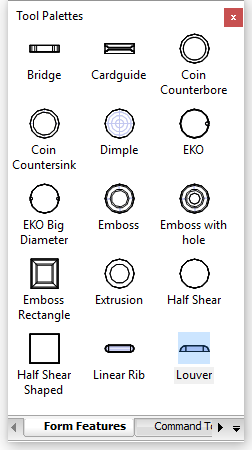
A library of parametrized sheet metal form features has been added. It is available from the Form Features tab of the Tool Pallettes panel. The library contains most commonly used form feature types. To insert a form feature to a sheet metal 3D solid drag the form feature icon from the Tool Palettes panel to a flange of the solid.
SmForm: command converts a selected set of faces to a form feature. A drawing file with a user-defined form feature can be saved and then inserted using the BMINSERT command.
SmConvert: command recognizes form features in imported geometry.
SmReplace: command allows replacing form features (including recognized ones) in sheet metal parts with form features from the built-in or user library.
SMFORMFEATUREUNFOLDMODE: system variable controls the appearance of the form features in 2D and 3D unfolded model representations.
Form features are added to sheet metal part by insertion on the existing flanges. The form features can be inserted by means of BmInsert command or by drag-and-drop process of required form feature from Form Features tab of Tool Palettes.
Make sure Dynamic Dimensions (DYN) and Dynamic UCS (DUCS) are active.
Do one of the following:
Click the Form Feature tool button
(![]() ) on the Sheet Metal toolbar.
) on the Sheet Metal toolbar.
Click the Form Feature tool button
( ![]() ) on the Sheet Metal ribbon bar.
) on the Sheet Metal ribbon bar.
Choose Insert Form Feature in theSheet Metal menu.
Type bminsert in the command bar, then press Enter.
The
Select file to insert dialog displays
the FormFeatures folder
C:\Users\<UserName>\AppData\Roaming\Bricsys\BricsCAD\V17x64\en_US\Support\DesignLibrary\SheetMetal\FormFeatures:
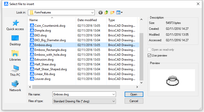
Select the desired form feature element from file list, then double
click or press the Open button.
Move the cursor over the flange face you want to
insert the feature in.
The dynamic UCS aligns to the selected face.
The orientation of the UCS depends on the edge you enter the
face.
Dynamic dimensions display from the origin of the UCS to the
insertion point of the form feature.
The command bar reads: Select insertion point or [Edit inserted entity/Rotate component/set Base point/Name/insertion Type/Flip/mUltiple] <0, 0, 0>:
(option) Choose an option (see the BmInsert command for more details):
To insert a the form feature do one of the following:
Repeat step 5 to insert another copy or press Enter to stop.
Editing the Parameters of a Library Form Feature
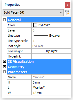
Form features in the form feature library are parametric components. Several parameters control their dimensions. Parameters to control the Length, Width, Height and Radius of the form feature are correspondingly named L, W, H and R. The thickness of the form feature is set equal to the thickness of sheet metal part automatically.
The parameters of a single form feature can be edited either in the Properties Bar or in the Mechanical Browser. Parameters of multiple form features can be edited in the Properties Bar only.
Check the Select Faces option of the SELECTIONMODES system variable, then click the feature(s) in the model.
Select the feature(s) in the Mechanical Browser, then press the space bar or right click and choose select in the context menu. Press and hold the Ctrl-key to select multiple form features.
A sheet metal part can have lots of different form features, which might complicates operations such as deletion or replacement, especially if only a selection of features, that meet certain conditions, need to be precessed. In order to help you to select form features more easily, the SmSelect command allows to select form features that are either identical to a selected feature or similar.
Select a parameter in the Parameters node in the
Properties Bar.
Select the form feature in Form node of the component structure tree.
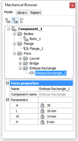
Select a parameters in the lower panel of the Mechancial Browser and type a new value.
Open a new drawing using Mechanical-metric.dwt as the template.
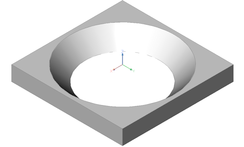
Create the 3D geometry of the form feature.
Execute the SmConvert
(![]() ) command.
) command.
Exectute the BmMech
(![]() ) command.
) command.
You are prompted: Name for mechanical component
<Component_2>:
Type a name for the form feature.
You are promted: Convert blocks and external references to
mechanical components? [Yes/No] <Yes>:
Select the No option.
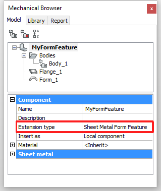
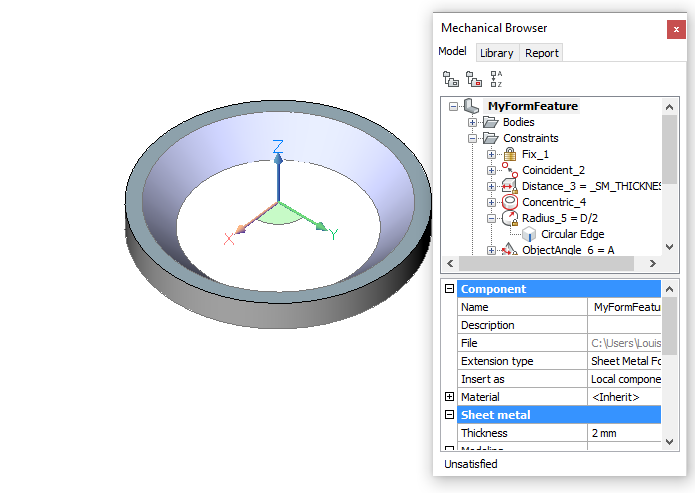
In the Extension type
field in Mechanical Browser select Sheet
Metal Form Feature.
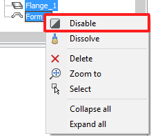
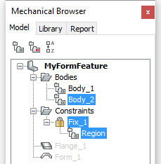
Select the Flange_1 and Form_1 features in the
Bodies node, then right click and
select Disable in the context
menu.
Create 2 new layers: UNFOLD_SYMBOL_UP and UNFOLD_SYMBOL_DOWN.
Turn layers 0 and UNFOLD_SYMBOL_DOWN Off and set layer UNFOLD_SYMBOL_UP Current.
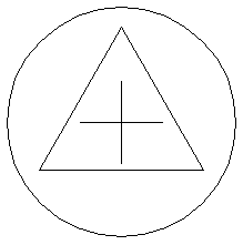
Create the unfold symbol, which will be placed on
the face the form feature is placed in.
Turn off the UNFOLD_SYMBOL_UP layer and turn on the UNFOLD_SYMBOL_DOWN layer. Set the UNFOLD_SYMBOL_ DOWN layer current.
Create the unfold symbol, which will be placed on
the opposite face the form feature is placed in.
Turn on layer 0 and turn the UNFOLD_SYMBOL_UP and UNFOLD_SYMBOL_DOWN layers off. Select the 0Set layer 0 current.
Save the drawing.
Creating Custom Parametric Form Feature
We will now parametrize the custom form feature we created in the previous procedure.
Two parameters are needed here: D for diameter of the bigger edge of the conical hole and A for angle of the face of the conical hole. In Sheet Metal we have a parameter _SM_THICKNESS which is equal to the thickness of the sheet metal part.
We will first create an auxiliary body for constraining on a new CONSTRUCTION layer. Make this layer current and switch off all other layers.
Create a Region on the
CONSTRUCTION layer in the XY plane of the WCS.
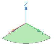
Apply a dmFix3D
constraint (![]() ) to the region.
) to the region.
Switch on layer 0.
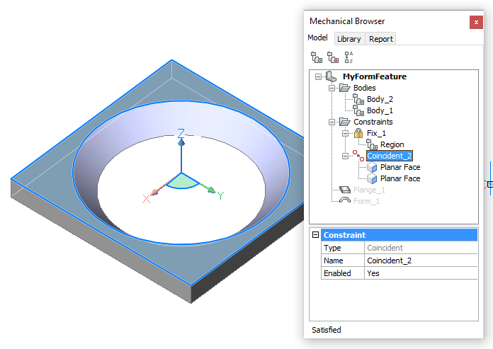
Apply a
dmCoincident3D constraint ( ![]() ) between the region face and
the flange top face.
) between the region face and
the flange top face.
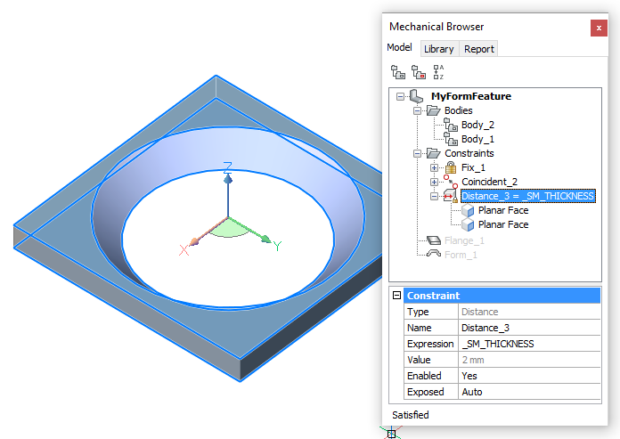
Apply a dmDistance3D
constraint (![]() ) between the flange top
and bottom faces.
) between the flange top
and bottom faces.
First select the top face, then hit the TAB key to select the
bottom face.
Accept the default value in the dynamic dimension.
Type _SM_THICKNESS in the Expression field of the Distance_3
constraint.
10. Since our Form Feature is conical we can modify flange from
parallelepiped to cylinder
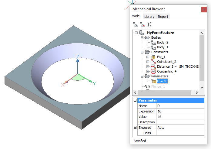
In the Mechanical Browser right click the feature name and
select Add new parameter in the
context menu.
Rename new parameter to D .
Select mm for the Units field.
Type 16 in the Expression field.
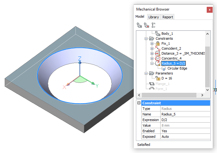
Apply a dmRadius3D
constraint (![]() ) to the top edge of the
conical face. Accept the default value in the dynamic
dimension.
) to the top edge of the
conical face. Accept the default value in the dynamic
dimension.
Type D/2 in the Expression field
of the Radius_5 constraint.
In the Mechanical Browser right click the feature name and
select Add new parameter in the
context menu.
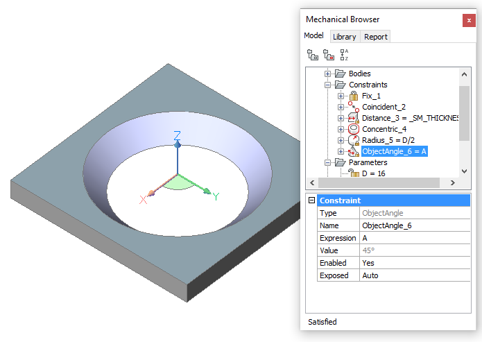
Rename new parameter to A .
Leave the Units field empty.
Type 45 in the Expression field.
Do one of the following to create a Cone Angle constraint to the conical face:
Launch the dmAngle3d
command (![]() ), then choose the Cone Angle constraint option, then select the
conical face.
), then choose the Cone Angle constraint option, then select the
conical face.
Hover over the conical face, then choose Cone Angle constraint (![]() ) in the Constraints command group in the Quad.
) in the Constraints command group in the Quad.
Accept the default value.
Type A in the Expression field of the ObjectAngle_6
constraint.
Since our Form Feature is conical we will modify the flange from parallelepiped to cylinder:
Draw a circle on top or the flange. The radius of the circle is 9 mm.
Select Enable Boundary Detection in the Settings panel on the Home tab in the Ribbon.
Place the cursor over the area between the circle and the square
edge of the flange, then choose Extrude (![]() ) in the Quad and move the
cursor downwards.
) in the Quad and move the
cursor downwards.
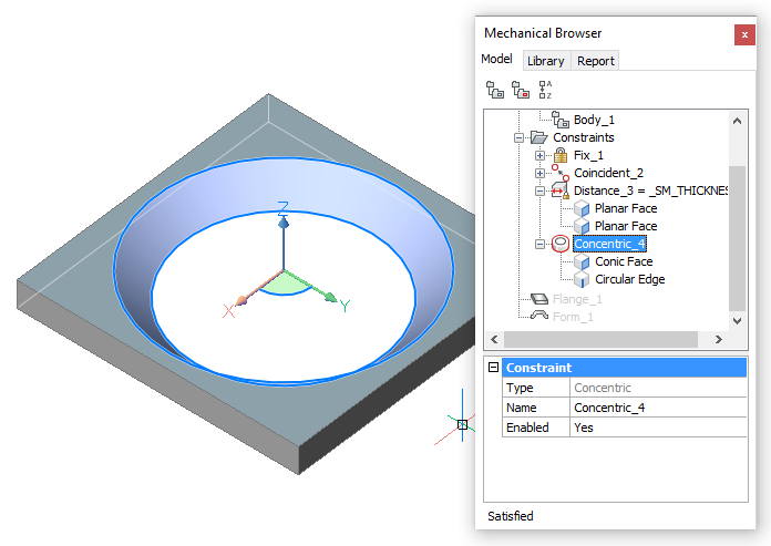
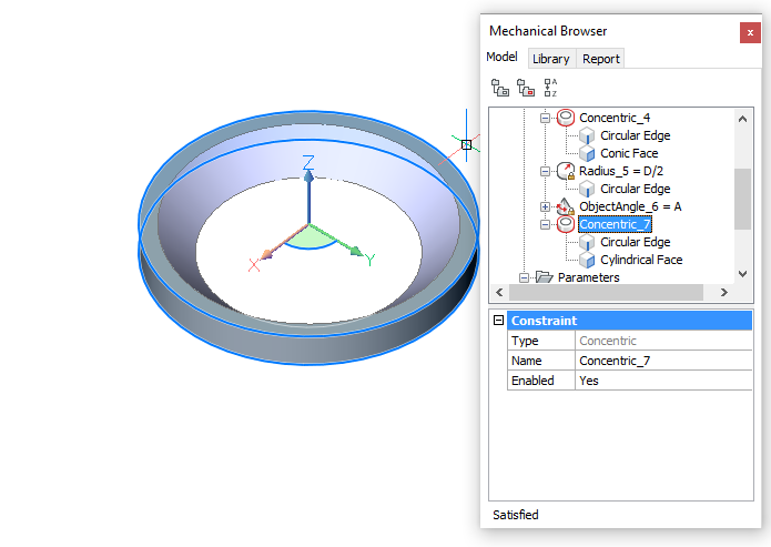
Apply a
dmConcentric3D constraint ( ![]() ) between the circular edge of
the region and the cylindrical face.
) between the circular edge of
the region and the cylindrical face.
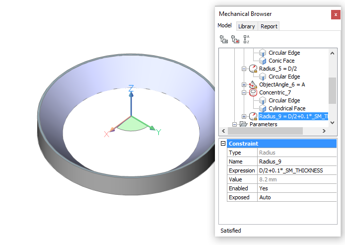
Apply a dmRadius3D
constraint (![]() ) to the cylindrical face.
Accept the default value in the dynamic dimension.
) to the cylindrical face.
Accept the default value in the dynamic dimension.
Type D/2+0.1*_SM_THICKNESS in the Expression field of the Radius_8 constraint.
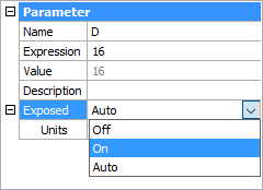
Set the Exposed field
of both parameter A and D On.
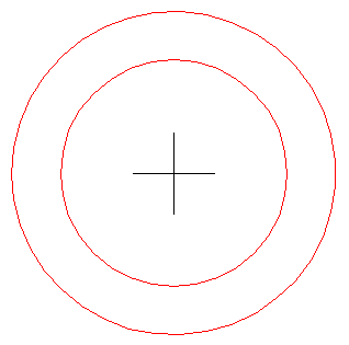
We will now create 2D constraints for the unfold symbols.
Make layer UNFOLD_SYMBOL_UP current and switch off all other layers.
Apply a GcFix constraint
(![]() ) to both crossing lines
indicating the center of the circles.
) to both crossing lines
indicating the center of the circles.
Apply a GcHorizontal
constraint (![]() ) to the horizontal center
line.
) to the horizontal center
line.
Apply a GcVertical
constraint
(![]() ) to the vertical center
line.
) to the vertical center
line.
Apply a GcConcentric
constraint (![]() ) between the two circles.
) between the two circles.
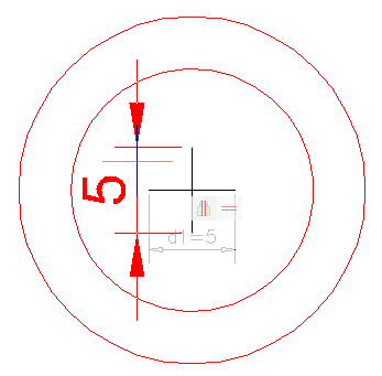
Apply a DcLinear
constraint (![]() ) between the endpoints of the
center lines. Accept the default value.
) between the endpoints of the
center lines. Accept the default value.
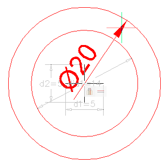
Apply a DcDiameter
constraint (![]() ) to both circles. Accept the
default value for dia1 (= inner circle) and dia2 (= outer circle)
.
) to both circles. Accept the
default value for dia1 (= inner circle) and dia2 (= outer circle)
.
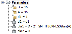
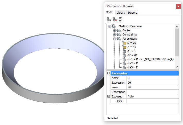
Adjust the Expression fields of the 2D constraints as follows:
d1 = 1
d2 = d1
dia 1 = D - 2*_SM_THICKNESS/tan(A)
dia 2 = D
Switch off the display of all layers, but layer 0,
then save the file.
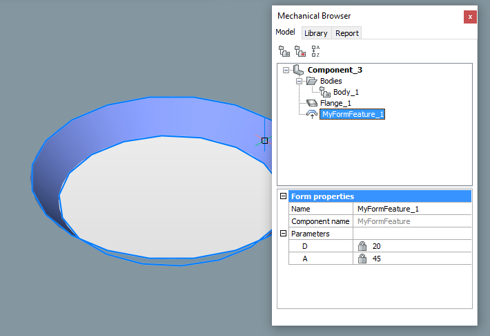
The form feature can now be used to make conical parametric openings in a sheet metal flange:
Use the Insert Form
Feature tool (![]() ), which launches the BmInsert
command.
), which launches the BmInsert
command.
Optionally: Add the form feature as a component to a tool palette.
| © Menhirs NV. All rights reserved. |