Do one of the following:
Click the Union
tool button (![]() ) on the X-Solids toolbar.
) on the X-Solids toolbar.
Choose Union in the X-Solids menu.
Type xunion in the command bar, then press Enter.
Commands: XUNION, XSUBTRACT, XINTERSECT, XCHAMFER, XFILLET, XSLICE, XCUT, XPUNCH, XTRIM, XARRAYR, XARRAYP
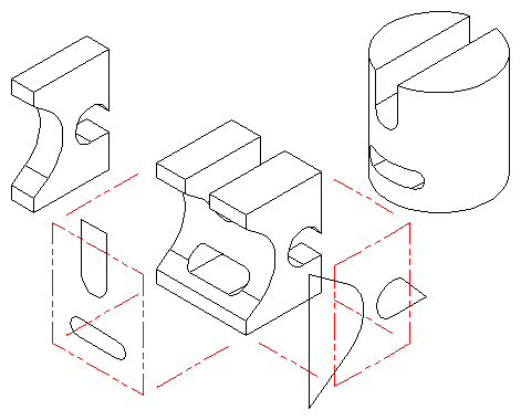
Complex solids are created by applying Boolean operations (union, subtract, intersect) and solid modifiers (chamfer, fillet, slice) to simpler solids, beginning with solid primitives.
When executing the XCUT, XPUNCH and XTRIM commands one extruded primitive is added to the composite solid each cutting or trimming profile that was used.
The Associative option of the XARRAYR command creates a composite solid as an array of solids by copying a primitive or composite solid in a rectangular pattern.
The Associative option of the XARRAYP command creates a composite solid as a polar array by copying and rotating a primitive or composite solid about an axis.
|
NOTE |
At first sight the result of the X-Solids boolean operation commands is similar to the result of the native Bricscad boolean operation commands. However, composite solids created by X-Solids boolean operation can be modified by the XSOLIDEDIT command, while composite solids created by the native Bricscad commands cannot. |
Use the XSOLIDEDIT command to:
modify the parameters of a primitive within a composite solid;
move, rotate, replace, copy or delete primitives within a composite solid;
change or delete solid modifiers, such as chamfer, fillets or slices, applied to the solid;
to modify the parameters of an associative rectangular or polar array;
Do one of the following:
Click the Union
tool button (![]() ) on the X-Solids toolbar.
) on the X-Solids toolbar.
Choose Union in the X-Solids menu.
Type xunion in the command bar, then press Enter.
The command bar reads: Select entities:
Select the X-Solids and/or Acis
solids you want to unify.
Press Enter or right click to stop selecting solids.
The selected solids are unified.
All selected solids are grouped as a single composite solid.
Do one of the following:
Click the Subtract tool button (![]() ) on the X-Solids toolbar.
) on the X-Solids toolbar.
Choose Subtract in the X-Solids menu.
Type xsubtract in the command bar, then press Enter.
The command bar reads: Select solids and regions to
subtract from...
Select entities:
Select the X-Solids and/or Acis
solids you want to subtract from.
Press Enter or right click to stop selecting solids.
The command bar reads: Select solids and regions to
subtract...
Select entities:
Select the X-Solids and/or Acis
solids you want to subtract.
Press Enter or right click to stop selecting solids.
The second selection set is subtracted from the
first selection set.
All selected solids are grouped as a single composite solid.
Do one of the following:
Click the Intersect tool button (![]() ) on the X-Solids toolbar.
) on the X-Solids toolbar.
Choose Intersect in the X-Solids menu.
Type xintersect in the command bar, then press Enter.
The command bar reads: Select entities:
Select the X-Solids and/or Acis
solids you want to intersect.
Press Enter or right click to stop selecting solids.
The intersection of the selected solid is
created.
All selected solids are grouped as a single composite solid.
Do one of the following:
Click the Fillet tool button (![]() ) on the X-Solids toolbar.
) on the X-Solids toolbar.
Choose Fillet in the X-Solids menu.
Type xfillet in the command bar, then press Enter.
The Create X-Solid Fillet dialog box displays.
To set the fillet radius do one of the following:
Type radius in the Radius field.
Click the Pick
button (![]() ).
).
The dialog temporarily closes.
You are prompted in the command bar to define a
circle.
When done, the dialog reopens.
Choose the Chain option.
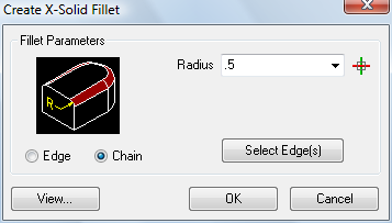
The image on the dialog reflects your choice.
(option) Choose the Edge option if you want to select single segments of chain.

The image on the dialog reflects your choice.
Click the Select
Edge(s) button or the OK
button.
The dialog closes.
A prompt menu displays:
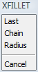
You are prompted in the command bar to select the edges you want to fillet.
Select the edges you want to fillet.
All selected edges highlight.
If you select a segment of a chain, all segments of the chain are
selected.
Choose Edge in the prompt menu or
type E and press Enter to select
single segments of a chain.
Press Enter or right click to stop selecting
edges.
The selected edges are filleted.
Do one of the following:
Click the Chamfer tool button (![]() ) on the X-Solids toolbar.
) on the X-Solids toolbar.
Choose Chamfer in the X-Solids menu.
Type xchamfer in the command bar, then press Enter.
The Create X-Solid Chamfer dialog box displays.
Define the chamfer distances:
The first distance (D1) is the
offset along the face you identify as the base face.
The second distance (D2) is the
offset along the adjacent face.
Do one of the following:
Type the distances in the D1 and D2 fields.
Click the Pick
button (![]() ).
).
The dialog temporarily closes.
You are prompted in the command bar: Right-mouse to
Pick/<Distance>:
Do one of the following:
Define a distance by specifying two points.
Right click. You are prompted in the command
bar: Select a line, arc, circle or edge:
Select an entity of your choice.
The length of the selected entity is copied to the chamfer distance
settings field.
(option) To chamfer separate edges of a solid choose the Edge option.
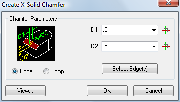
The image on the dialog reflects your choice.
Click the Select
Edge(s) or the OK button.
The dialog box closes.
Click the edge you want to chamfer.
The base face of the selected edge highlights.
You are prompted in the command bar: Next/<Accept>:
Right click to accept the highlighted face as
the base face
or
Choose Next in the prompt menu or
type N + Enter to choose a different
base face.
(option) Select more edges of the base face.
Press Enter to create the chamfer.
All selected edges are chamfered.
(option) To chamfer all edges of a face choose the Loop option.
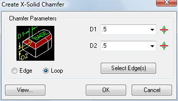
The image on the dialog reflects your choice.
Click the Select
Edge(s) or the OK button.
The dialog box closes.
Click an edge of the face you want to
chamfer.
The base face of the selected edge highlights.
You are prompted in the command bar: Next/<Accept>:
Right click to accept the highlighted face as
the base face
or
Choose Next in the prompt menu or
type N + Enter to choose a different
base face.
Press Enter to create the chamfer.
All edges of the selected base face are chamfered.
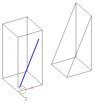
The XSLICE command cuts an ACIS solid or an X-solid with a plane; the result is a 3D solid cut in two. You can choose whether to keep both parts or just one.
To slice a solid:
Do one of the following:
Click the Slice
tool button (![]() ) on the X-Solids toolbar.
) on the X-Solids toolbar.
Choose Slice in the X-Solids menu.
Type xslice in the command bar.
The command bar reads: Select solids to slice:
Select one or more solids.
Right click or press Enter to stop selecting solids.
The Create X-Solid Slice dialog box displays:
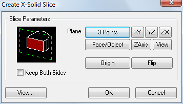
Click an option button to define the slicing
plane.
The options are:
3 Points: You are prompted in the command bar to define a plane by 3 points.
XY: The slicing
plane is parallel to the XY-plane of the current UCS.
Click the Origin button to define the
position of the plane.
YZ: The slicing
plane is parallel to the YZ-plane of the current UCS.
Click the Origin button to define the
position of the plane.
ZX: The slicing
plane is parallel to the ZX-plane of the current UCS.
Click the Origin button to define the
position of the plane.
Face/Object:
You are prompted to select a 2D entity in the drawing.
The plane through the selected entity will be the slicing
plane.
All 2D linear entities such as lines, polylines, arcs and circles
are accepted.
ZAxis: Define a
plane by two points. The plane passes through the first point and
is perpendicular to the direction defined by the two points.
Your are prompted in the command bar:
Point on plane <0,0,0>: specify to origin point of the plane.
Point on Z-axis (normal) of the plane: specify the Z-direction of the plane.
View: The
slicing plane is parallel to the current view.
Click the Origin button to define the
position of the plane.
(option) Click the Origin button to parallel move the slicing plane
.
You are prompted in the command bar: Slice origin:
Specify a new origin point for the slicing plane.
To choose the part of the original solid you want to keep, do one of the following:
Check the Keep Both Sides option to keep both parts of the solid.
Uncheck the Keep Both Sides option, then click the Flip button to decide which part you want to keep.
Click the OK button to execute the slicing operation.
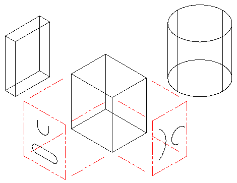
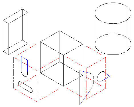
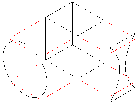
The XCUT command cuts 3D solids using 2D profiles as cutting tools. The command first checks for solids among the currently selected entities; if no solids are pre-selected, you are prompted to choose one or more solids by the usual Bricscad selection methods.
The composite solid created by the XCUT command will contain one extruded primitive for each cutting profile that was used. The XSOLEDIT command can then be used on the new solid as with any other composite solid.
Do one of the following:
Click the Cut
tool button (![]() ) on the X-Tools toolbar.
) on the X-Tools toolbar.
Choose Cut in the X-Solids > Tools menu.
Type xcut in the command bar.
The command bar reads: Select solids to cut:
Select the solids to cut.
Right click or press Enter to stop selecting solids.
The selection set is filtered for solids, other entity types are
ignored.
The command bar reads: Select cutting shapes:
Select one or more 2D entities.
Right click or press Enter to stop selecting cutting shapes.
Cutters can be any planar curves (arcs, circles, ellipses, open or
closed polylines), region entities and lines (*).
After cutter selection is complete, any open cutter shapes will be automatically closed by extending straight line segments from and tangent to each end of the profile until they intersect to form a closed profile. If the extended segments are parallel or diverge they will be extended beyond the boundaries of the selected solids and then closed.
After all cutters are closed, the first cutter will be projected along the normal of the cutter plane through the selected solids and subtracted from the solids.
The command bar reads: Left-mouse or 'F' for Flip/Both/<Accept>:
The Xcut prompt menu displays:
![]()
Do one of the following
Choose Accept in the prompt menu or right click or press Enter to accept the cut as performed.
Choose Flip in
the prompt menu, type F + Enter
or left click if the portion of the solid that you want to
keep has been removed.
The opposite portion of the solid will be removed.
Choose Both in the prompt menu or type B + Enter to keep both portions of the solid .
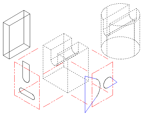
When the first cutting operation is completed, the process will be repeated for each profile until all cuts are executed.
(*) Lines may also be used as cutting shapes but only under certain conditions. The XCUT command normally creates cutting shapes by extruding planar 2D entities along the normal of the planar entity. Lines, however, do not always have a normal. Lines created entirely within the plane of the then-current UCS are created with a normal that matches the Z-direction of that UCS. When such lines are used as cutting shapes, they are first turned into closed polylines oriented perpendicular to their normal and then extruded along their normal to complete the cutting shape. This is true regardless of the current UCS orientation when the XCUT command is run.
The XPUNCH command cuts 3D solids using 2D profiles as cutting tools. The command first checks for solids among the currently selected entities; if no solids are pre-selected, you are prompted to choose one or more solids by the usual Bricscad selection methods.
The composite solid created by the XPUNCH command will contain one extruded primitive for each cutting profile that was used. The XSOLEDIT command can then be used on the new solid as with any other composite solid.
Do one of the following:
Click the Punch
tool button (![]() ) on the X-Tools toolbar.
) on the X-Tools toolbar.
Choose Punch in the X-Solids > Tools menu.
Type xpunch in the command bar.
The command bar reads: Select solids to punch:
Select the solids to punch.
Right click or press Enter to stop selecting solids.
The selection set is filtered for solids, other entity types are
ignored.
The command bar reads: Select cutting shapes:
Select one or more 2D entities.
Right click or press Enter to stop selecting cutting shapes.
Cutters can be any planar curves (arcs, circles, ellipses, open or
closed polylines), region entities and lines (see XCUT).
As different from the XCUT command, the XPUNCH command completes immediately if all originally-selected cutting shapes are closed profiles.
If one or more cutting shapes are open profiles, those profiles will be automatically closed and the XCUT procedure is used to process such profiles.
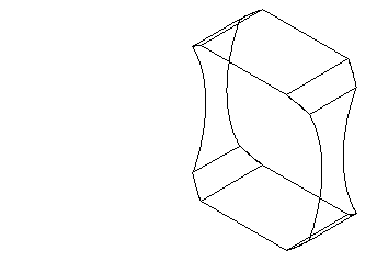
The XTRIM command trims 3D solids using 2D profiles as trimming tools. The command first checks for solids among the currently selected entities. If no solids are pre-selected, you are prompted to choose one or more solids by the usual Bricscad selection methods.
The composite solid created by the XTRIM command will contain one extruded primitive for each cutting profile that was used. The XSOLEDIT command can then be used on the new solid as with any other composite solid.
Do one of the following:
Click the Trim
tool button (![]() ) on the X-Tools toolbar.
) on the X-Tools toolbar.
Choose Trim in the X-Solids > Tools menu.
Type xtrim in the command bar.
The command bar reads: Select solids to trim:
Select the solids to tirm.
Right click or press Enter to stop selecting solids.
The selection set is filtered for solids, other entity types are
ignored.
The command bar reads: Select cutting shapes:
Select one or more 2D entities.
Right click or press Enter to stop selecting cutting shapes.
Cutters can be any planar curves (arcs, circles, ellipses, open or
closed polylines), region entities.
After trimmer selection is complete, each trimming profile will be projected along the normal of the profile plane through the selected solids and all material outside the path of the projected profiles will be removed from the solids.
The XTRIM command completes immediately if all originally-selected cutting shapes are closed profiles.
If one or more cutting shapes are open profiles, those profiles will be automatically closed and the XCUT procedure is used to process such profiles.
Do one of the following:
Click the Rectangular
Array tool button (![]() ) on the X-Tools toolbar.
) on the X-Tools toolbar.
Choose Rectangular Array in the X-Solids > Tools menu.
Type xarrayr in the command bar.
The command bar reads: Select Entities:
Select one or more primitive or composite solids.
Right click or press Enter to stop selecting solids.
The Create Rectangular Array dialog box displays:
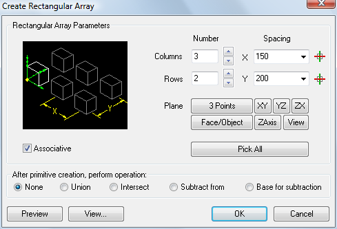
(option) Check the Associative option.
If checked, the array is created as a composite solid.
(option) Click the Pick All button to define all array parameters in the drawing.
To specify the number of columns and rows in the array, do one of the following:
Type the number in the Columns and Rows fields.
Press the 'up' and 'down' buttons until the desired number displays.
To specify the X- and Y-spacing distances, do one of the following:
Type the distance in the X and Y settings fields.
Choose the distance from the previously used distances list.
Click the Pick button
(![]() ) to specify the distance in the drawing.
) to specify the distance in the drawing.
(option) By default the array is created in a plane
that is parallel to the XY-plane of the current UCS (XY option).
Click one of the Plane option buttons
to create the array in a different plane.
(option) Click the View... button to manipulate the view.
(option) Click the Preview button.
(option) Choose an After primitive creation operation to be executed after the X-Solid box is created.
Click the OK button
to create the rectangular array.
If the arrayed solids overlap each other, they are unified if the
Associative option was checked.
Do one of the following:
Click the Polar
Array tool button (![]() ) on the X-Tools toolbar.
) on the X-Tools toolbar.
Choose Polar Array in the X-Solids > Tools menu.
Type xarrayp in the command bar.
The command bar reads: Select Entities:
Select one or more primitive or composite solids.
Right click or press Enter to stop selecting solids.
The Create Polar Array dialog box displays:
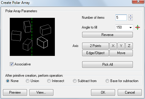
(option) Check the Associative option.
If checked, the array is created as a composite solid.
(option) Click the Pick All button to define all array parameters in the drawing.
To define the number of items, do one of the following:
Type the number in the Number of items field.
Press the 'up' and 'down' buttons until the desired number displays.
To set the angle, do one of the following:
Type the angle in the Angle to fill field.
Choose the angle from the previously used angles list.
Click the Pick button
(![]() ) to specify the angle in the drawing.
) to specify the angle in the drawing.
(option) Click the Reverse button to reverse the angle direction.
To define the axis do one of the following:
2 Points: You are prompted to specify two points.
X, Y, Z: Uses the X-, Y- or Z-axis of the current UCS.
Edge/Object: You are prompted to select a linear entity (line, ray, infinite line, ...) or an edge.
(option) Click the Move button to move the axis.
You are prompted in the drawing to specify a point. The axis is
moved parallel.
(option) Click the View... button to manipulate the view.
(option) Click the Preview button.
(option) Choose an After primitive creation operation to be executed after the X-Solid box is created.
Click the OK button
to create the polar array.
If the arrayed solids overlap each other, they are unified if the
Associative option was checked.
| © Menhirs NV. All rights reserved. |