Commands: XBOX, XCYLINDER, XCONE, XSPHERE, XTORUS, XWEDGE, XEXTRUDE, XREVOLVE, XSWEEP, XARRAYR, XARRAYP
The solid creation commands have dialog-driven interfaces. The dialog boxes make solids easier to use by presenting all the parameters and options at once. Even if you have considerable experience using Bricscad solids and X-Solids, you will probably notice some options that you didn’t know existed.
|
NOTE |
The XDIA command can suppress the X-Solids command dialogs and thus force command-line interpretation |
To make them easy to use, the X-Solids dialogs have certain common features.
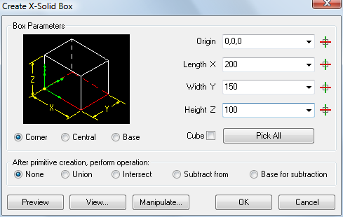
The Create X-Solid Box dialog illustrates the features you’ll see on most Create X-Solids dialogs.
The creation dialogs have an image in the upper left to indicate the kind of solid being created. It is a static image, not scaled to the size you are creating. The ECS (Entity Coordinate System) tripod, drawn in green, shows where the entity’s origin will be located. The red rectangle indicates the location of the base shape. Click the Corner, Central or Base radio buttons to relocate the solid's origin.
The object's parameters appear next to the illustration. All X-Solids dialogs remember the last value of all parameters. Some parameters are shared by various dialog boxes. For example, the Height Z parameter applies to the Create X-Solid Box, X-Solid Cylinder, X-Solid Cone and X-Solid Wedge dialogs. All previously used values in the current Bricscad session can be chosen from a drop-down list.
The solid creation dialogs have a Pick All button that temporarily closes the dialog and prompts you in the command bar. In this way you can, for example, drag a rectangle to define a box, or a circle to define a cone or cylinder. When input is complete, the dialog reopens with the values you specified.
Click the Pick button (![]() ) of a parameter to define the value graphically in the
drawing. The dialog box closes temporarily and you are prompted in
the command bar. If you first click the Pick
Origin button, a preview of the solid displays at the
selected location.
) of a parameter to define the value graphically in the
drawing. The dialog box closes temporarily and you are prompted in
the command bar. If you first click the Pick
Origin button, a preview of the solid displays at the
selected location.
Click the Manipulate... button to move or rotate the solid being created.
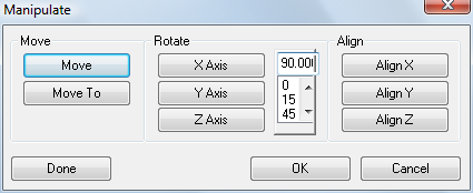
Move: The dialog temporarily closes. Your are prompted in the command bar: Base point of displacement:
Move To: The dialog temporarily closes. The origin point of the solid being created is attached to the cross hairs. You are prompted in the command bar: Move to:
Rotate: Either type an angle in the Angle field or choose 0, 15, 45 or 90 from the angle list, then click an axis button. The solid being created is rotated about the axis chosen
Align: Click one of the align buttons, e.g.
Align X. The dialog temporarily
closes. Your are prompted in the command bar: Pick/<First point to align the X axis>:
Do one of the following:
Specify two points to define the direction of the solid's X-axis.
Choose the Pick option in the prompt box or type P, then press Enter and select a line or polyline segment to align the solid's X-axis with.
OK: The Manipulate dialog closes. The Create X-Solid dialog reopens.
Done: The solid is created.
Cancel: The create X-Solid command is aborted.
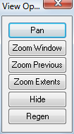
Click the View... button to open the View Options list.
Under After primitive creation perform operation you can select an operation you want to perform with the newly created primitive.
The options are:
None: No operation is executed after the OK button is clicked.
Union: You are prompted in the command bar: Select solids to UNION with the new solid:
Intersect: You are prompted in the command bar: Select solids to INTERSECT with the new solid:
Subtract from: You are prompted in the command bar: Select solids from which to SUBTRACT the new solid:
Base for subtraction: You are prompted in the command bar: Select solids to SUBTRACT from the new solid:
| © Menhirs NV. All rights reserved. |