Works with Bricscad (Windows) Platinum
Creates a wedge as a 3D X-Solid .
Accessing the Command
command bar: xwedge
menu bar: X-Solids | Wedge
toolbar: X-Solids | ![]()
: xwedge
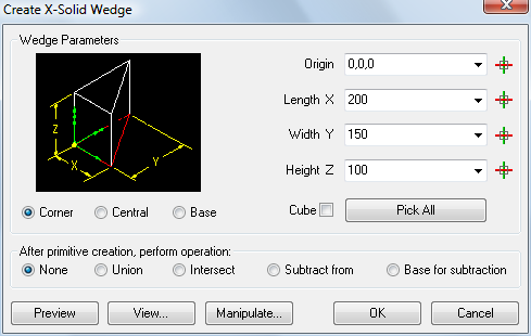
Displays a dialog box:
Command Options
|
Option |
Description |
|
Specifies the x,y,z coordinates of the origin point:
|
|
|
Width Y Height Z |
Specify the dimensions of the wedge: Length X: parallel to the X-axis of the current UCS Width Y: parallel to the Y-axis of the current UCS Height: parallel to the Z-axis of the current UCS
|
|
Disables the Width Y and Height Z fields. Creates a wedge with equal sides using the Length X field. |
|
|
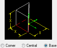
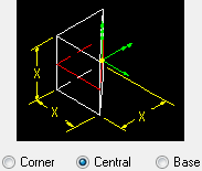
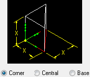
The Create X-Solid Wedge dialog box temporarily closes. Prompts you in the command bar: Base/ceNter/<Corner of box> <0,0,0>: Specify the dimensions of the box in the drawing.
|
|
|
Displays a preview of the wedge in the drawing in dashed lines. |
|
|
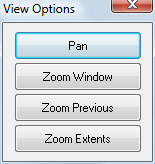
The Create X-Solid Wedge dialog box temporarily closes. Displays the View Options dialog box:
|
|
|
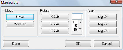
The Create X-Solid Wedge dialog box closes. Displays the Manipulate dialog box to Move, Rotate or Align the X-Solid wedge.
Move: Prompts you in the command bar to specify the displacement vector by clicking two points. Move To: Prompts you in the command bar to move the origin point of the X-Solid wedge. Rotate: Type an angle in the Angle field or choose an angle in the list box, then click an axis button to rotate the X-Solid wedge. Align: Aligns the X, Y or Z-axis of the X-Solid wedge. Prompts you in the command bar to specify two points. The X-Solid wedge is rotated about its origin. Done: Creates the X-Solid wedge. OK: Reopens the Create X-Solid wedge dialog box. Cancel: Aborts the XWedge command. |
|
|
Creates the X-Solid wedge. |
|
|
Aborts the the XWedge command. |
|
|
Launches the XUnion, XIntersect or XSubtract command to be executed using the newly created X-Solid wedge. You are prompted in the command bar to select one or more other solids. |
Grips Editing
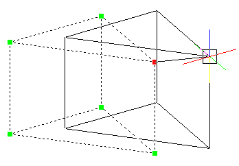
X-Wedges can be edited directly through grips:
Select the wedge. Notice that it has many grips.
Drag any grip to move the wedge. (All six grips perform the same function: move.)
Related Commands
Box - creates 3D boxes as Acis solid models.
Wedge - creates a wedge as a polyface mesh (Classic); creates a wedge as a 3D solid (Pro and Platinum).
XBox - creates a three-dimensional X-Solid box.
XCone - creates a cone as a 3D X-solid.
XCylinder - creates a wedge as a 3D X-Solid.
XExtrude - extrudes 2D entities to X-solids.
XRevolve - revolves 2D closed entities to turn them into 3D X-Solids.
XSphere - creates a sphere as a 3D X-Solid.
XSweep - Extrudes 2D entities along a path to X-solids.
XTorus - creates a torus as a 3D X-Solid.
| © Menhirs NV. All rights reserved. |