Below is a brief description of the enhancements and new features. Click on the hyperlink keywords for a detailed description.
Some features or commands might not be available yet on the Linux platform. Please check the Command Reference guide.
MENUS and TOOLBARS have been extended and reorganized.
Click here to read the Bricscad Release Notes (Internet connection needed).
PUBLISH command: Allows to print a sheet list (= a list of model space or paper space layouts) to a printer. Saves a sheet list to a file.
PUBLISHALLSHEETS system variable: Specifies whether to load the contents of the active document or of all open documents in the Publish dialog box.
LAYER FILTERS: use expressions and layer properties to filter out sets of layers, and store filters for reuse. The option to hide or show XREF layers has been removed. The layer toolbar listens to the current layerfilter.
SHOWLAYERUSAGE system variable: shows layer information in the Drawing Explorer - Layers dialog box.
LAYER EXPLORER: for layouts and paper space viewports, columns were added for ViewPort (VP) Color, VP Linetype, VP Lineweight and VP Plot Style.
XOPEN command: Opens an external reference. The command is available from XREF context menu and from the Drawing Explorer - External References dialog box.
DRAWING EXPLORER - DRAWINGS: Possibility to browse and insert blocks from unopened drawings into the current drawing. Drawings in the Folders tab are available.
EXPBLOCKS: Added Description column (block comments) to blocks detail view.
LOOK FROM toolbar: TopBottom flyout is added to the middle button of the Look From toolbar. The first button is the same as before, i.e. rotate the view to top view, the second button rotates the view to the bottom view.
PRINT: A Print To File checkbox is added to the Print dialog.
TABLEEXPORT: The Export Table option is added to the context menu when one table entity is selected.
TOOLPALETTES: On a tool palette you can add blocks, hatches and commands in a tabbed window.
DMRIGIDSET3D: Allows to define a set of entities or subentities as a rigid body.
Implemented drag and drop for rearranging layout tabs.
The sort order of the layout names in the Status bar has been fixed.
FILE DIALOG: All 5 icons in the Places bar at the left of the dialog are now customizable in the SETTINGS dialog (Program Options > Files > File Dialogs > Places bar), 4 of them can be chosen from a combo with predefined options, the fifth is still initialized from DRAWINGPATH setting as before.
DRAWING EXPLORER > LAYERS: Merge To ... option in the Edit menu to merge the content of two layers.
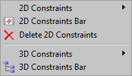
2D-CONSTRAINED drawing:
Geometric Constraints: Applies geometric relationships between entities or points on entities.
Dimensional Constraints: Applies dimensional constraints to entities or points on entities.
3D Modeling option in the New Drawing Wizard procedure and related 3D template drawings.
3D-CONSTRAINED drawing
Enhanced 3D modeling features in Bricscad V12, are enabled or disabled by a set of preferences and system variables, both existing and new ones. All these settings are editable in the Settings dialog, either by browsing to them, or typing a part of their name in the search field on top of the dialog. Below are recommended values for these settings. These are the default values, but if you experience problems when working in 3D, you might want to check their value.
PREVIEWSUBENTS: set to 3 (check faces and edges on) to have highlighting of faces and edges when the mouse hovers over solids. You can toggle between highlighting edges and faces, or the full solids, by clicking the 'SUB' button in the status bar or by pressing CTRL+F12.
The QUAD
cursor menu, aka the Quad is an alternative to grip-editing of
entities, offering a (much) richer set of editing operations while
requiring less clicks, without cluttering the screen with loads of
grip-glyphs.
QUADDISPLAY: when the mouse hovers over a closed planar 2D
entity or a solid, the Quad cursor menu will display. You can
toggle the display of the Quad (and its usage) On and Off by
clicking the 'QUAD' button in the
Status bar or by pressing F12.
Direct modeling commands are: dmChamfer, dmDelete, dmExtrude, dmFillet, dmMove, dmPushPull, dmRevolve and dmRotate.
3DCONTEXT and 2DCONTEXT commands switch the modeling environment On and Off. Toolbuttons to launch the commands are added on the View toolbar.
DRAWORDER commands:
HATCHTOBACK: Sets the draw order of all hatch entities in the drawing to display behind all other entities.
TEXTTOFRONT : Sets the draw order of all texts and dimensions in the drawing to display in front of all other entities.
Support for user defined hatch patterns.
Support TRIM operation for hatches and gradient fills. Associativity is maintained whenever possible.
Create, edit and manage Page Setup objects in the Drawing Explorer and applying named page setups when printing.
Page Setup explorer allows to copy page setups between drawings.
PSETUPIN and -PSETUPIN commands offer additional ways to import page setups from other drawings.
Replaced Adobe PDF lib with FLYSDK lib from Visual Integrity.RENDERED MODE: working in rendered mode has been improved with highlighting of faces and edges, grips, dynamics.
Strongly improved snap performance.
Improved redraw speed.
Ctrl-R keyboard shortcut switches between viewports in Model Space and Paper Space layouts.
Ctrl + LeftMouseButton no longer triggers Real Time Orbit, instead it is used for selection/deselection of entities. This was done to enhance selection of sub-entities (e.g. edges of solids). Please use Shift + MiddleMouseButton for Real Time Orbit.
Display settings are saved in a named style in the Drawing Explorer. Visual styles features that are not supported yet are indicated in the Drawing Explorer - Visual Styles dialog.
Rendered modes now have enhanced highlighting of faces and edges, grips, dynamics.
Command NEWWIZ: new 3D option
creates a visual style MODELING and a view HOME which uses this
visual style.
The new 2DCONTEXT and
3DCONTEXT
commands let you switch between the 2D drafting and 3D modeling
visual style. These commands are available in the View menu and the View toolbar.
Command SHADEMODE has been adapted to use visual styles, and has been extended with visual style Modeling, recommended for 3D modeling, and High Quality, for rendering.
SECTIONS
SECTIONPLANE: Creates persistent section definitions. Jogged (multi-segment) section planes are not yet supported, but will be added soon.
SECTIONPLANESETTINGS: Section objects have 2D settings, 3D settings and Live section settings, which are managed in the Drawing Explorer.
SECTIONPLANETOBLOCK allows to generate 2D or 3D cutaway section geometry, according to the sectionplane settings. The result can be stored in a block or in a new drawing.
LIVESECTION: when a section object is set 'live', intersected objects, intersection fill and cutaway geometry are displayed in the drawing according to the live section settings. When the section object is moved or modified, section results are updated on the fly.
New Sections toolbar.
RASTER ENGINE: New Imagine multi-resolution raster engine, designed to swiftly handle large images.
Improved redraw speed for images that use non-default settings for Contrast, Brightness or Fade.
Image display is anti-aliased now.
Improved quality of bitonal image display.
Caching and compression will be added in the coming months to further improve the user-experience.
MODELERPROPERTIES and -MODELERPROPERTIES commands to control various settings of the Acis modeler. FACETRES is now used for display by default.
QTEXT: toggles between normal text display and simplified text display (as rectangles).
SCALELISTEDIT command allows to extend the scale lists used in Print dialog and Viewport properties.
TEIGHA 3.5 UPDATE: invisible at the surface, important code modifications took place: we upgraded the underlying ODA DwgDirect V2.06 libraries to ODA Teigha V3.05, bringing along hundreds of fixes.
ADT: object enabler for Autocad Architectural Desktop.
ODA-specific:
AcisSaveAsMode, DxfTextAdjustAlignment, PLINECACHE,
R12SaveAccuracy, R12SaveDeviation, SAVEROUNDTRIP.
Acad-compatible:
CAMERADISPLAY, CAMERAHEIGHT, CMATERIAL, DGNFRAME, DGNOSNAP,
DIMTXTDIRECTION, DWFFRAME, DWFOSNAP, DXEVAL, EXPORTMODELSPACE,
EXPORTPAPERSPACE, EXPORTPAGESETUP, FIELDDISPLAY, FRAME,
GEOLATLONGFORMAT, GEOMARKERVISIBILITY, GRIPDYNCOLOR, GRIPTIPS,
IMAGEFRAME, INTERFERECOLOR, INTERFEREOBJVS, INTERFEREVPVS,
LIGHTGLYPHDISPLAY, MESHTYPE, PREVIEWTYPE, PSOLHEIGHT, PSOLWIDTH,
REALWORLDSCALE, SAVEFIDELITY, SKYSTATUS, STEPSIZE, STEPSPERSEC,
TILEMODELIGHTSYNCH, UCSVIEW.
Updated: DIMTAD (range 0-4 instead of 0-3).
OSNAPZ: The OSNAPZ system variable is supported. If this variable is on, Entity Snap markers are transformed correspondingly the current ELEVATION value, except for extension and polar snapping.
All user preferences now can be modified from the command line (like system variables).
In V12 menu items and toolbar buttons are reorganized, a few menus and toolbars are added.
See the User Guide / User Interface / Toolbars for a list of all Bricscad V12 toolbars.
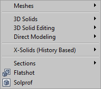
Model menu: All 3D related commands are grouped in this new menu:
Meshes: commands to create 3D mesh surfaces.
3D Solids: commands to create Acis Solids (Pro and Platinum only).
3D Solid Editing: commands to edit Acis Solids (Pro and Platinum only).
Direct Modeling: new direct modeling commands (Pro and Platinum only).
X-Solids (History Based): X-solids commands (Platinum only - X-Solids menu in V11)
Sections: new SECTIONPLANE, SECTIONPLANETOBLOCK and LIVESECTION commands (Pro and Platinum only).
Parametric menu: this new menu contains all 2D and 3D constraints commands.
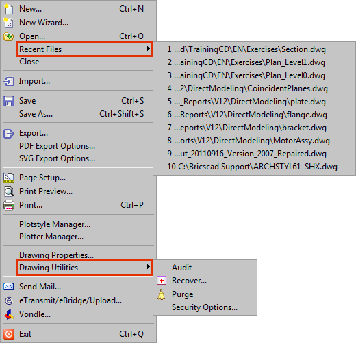
File menu:
Recent Files is a flyout in the top section of the menu
Audit, Recover, Purge and Security Options are grouped the Drawing Utilities flyout.
View menu: new 2D Context and 3D Context items are added.
Insert menu: the items are reorganized and the Layout flyout is removed. The Hyperlink item is added.
Settings menu: the Drawing Explorer categories have been moved and grouped as a flyout of the Tools menu.
Tools menu:
Drawing Explorer categories are grouped as a flyout
Attribute tools are grouped in a flyout.
Draw Order and External Reference Editing flyouts are added.
Draw menu:
Items are reorganized.
Text and Mtext items are added.
Meshes and Solids have been moved to the new Model menu.
Dimensions menu: the order and grouping of the items has changed.
Modify menu:
Items are reorganized.
Image editing tools are added in the Raster Image flyout.
FLATSHOT and SOLPROF commands have been moved to the new Model menu.
Edit Text has been removed. The DDEDIT command is launched when double clicking a text entity.
Images menu: Insert Image sits in the Insert menu, image editing tools are moved to the Raster Image flyout of the Modify menu. Image management can be found in the Tools / Drawing Explorer menu.
X-Solids menu: X-Solids items are moved to the X-Solids (History Based) item in the new Model menu.
| © Menhirs NV. All rights reserved. |